
Page 257 - Estimators Piping Man Hour Manual
P. 257
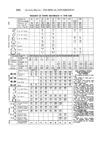
232 Section Eleven—TECHNICAL INFORMATION
WEIGHTS OF PIPING MATERIALS—S" PIPE SIZE
, rfihedule No 20 30 Htd 60 xs 100 120 140 XXS 160 _ 4 1 _
40
80
l>esif,nati^i
Wail
z 1 hit kne-« In 250 277 322 406 500 593 718 812 .875 .906 _L4
Pipe ~Ibs Ft 22 36 24.70 2855 35.64 434 509 606 678 724 74.7
\\atcr Ltw Ft 2248 22.18 21 69 20.79 19.8 IS. 8 176 16 7 16.1 15.8
/? 46 69 114 117
(if L R 'tO 1 Ihovv 2 2 2 2
. O S R MO" I'lhow 1.3 46
31
1.3
^
5
1
23 34 55 56
I R 45 Llbow .8 .8 .8 .8
1 .
r 54 76 i 118 120
0 f^\ j (.p 1.8 1.8 1.8 ! 8 — -
£ L~LJ i
o XV 1 55 216
1*3 -Ctt^ **
s Q~3 1 ateral 3.8 3.8 j
U.9 20 32 33
Reducer .5 .5 .5 .5
11.3 16.3 31 32
^ Cap 1 1 1 1
Tcmperature Range °F to 260° 460^60 360-440 44<W2fi 525-600 600-700 700-800 800-900 900-100« I
^% Thickness In. IVt 1H 2 2»/i 3
g Magnesia U»/Ft 4.05 5 30 7.70 10.3 12.5
3 * ^onibina- Thickness lu 3 3H 4 4H 5 5H 6
g tion Lbs, Ft 16.9 19.6 23.1 26.7 32.8 38.3 43.4
Cali'ium Thickness— In 1H uT~T m iy t 2 2 2H 3 3H 4 4« 5
Silicate Llw, Ft 4.06 4.06 4.06 4.06 5.56 5.56 7.61 9.38 11.3 133 154 17.6
Cast Iron Steel
Pressure Hating SEE GENERAL NOTES
psi 125 250 150 300 400 600 900 1500 2500 FOR MATERIALS
f!<r<"we<f or 34 64 33 67 82 135 206 319 601 NOT SHOWN
Slip-On 1.5 1.5 1.5 1.5 1.5 1.5 1.5 1.5 1.5 All vreighte are shown in bale
33 66 87 117 193 280 613 'The weight of steel pipe b
ItCfe Welding Nock 1.5 1.5 1.5 1.5 1.5 1.5 1.5 per lin«JMT foot.
36 70 86 139 227 354 595 For Boiler Feed Piping, a«k
ttift Lap Joint 1.5 1.5 1.5 1.5 1.5 1.5 1.5 the w sight of water to the
of steel pipe,
45 S3 48 90 115 159 231 362 649 W
1t
pipe
cfci^^ Blind 1.5 1.5 1.5 1.5 1.5 1.5 1.5 1.5 1.5 nesses and conditions per thick-
covering
weight* indicate
the
linear
average
157
FITTINGS S I K K 40 " h Ibuw 117 201 4.5 238 310 435 639 995 foot wirB, cement, canvas, bands is
include all
an d
allowances
4.7
4.7
4.5
5.2
5.7
5.4
5
for
and
psunt.
listed
236
thick-
The
152
283
202
neos
of oombiimtion
covering
5.3
<K)
5.3
,5,3
5 3
1 Ibow
and
of
inner
sui•n
the
the
FLANCF0 Dfc^fc 45 Klt>. w 3.9 171 3.9 203 215 360 507 1465 the Pipe imd covering not temperature
127
lOi
870
outer lilyer thickness,
44
4.8
4.5
4
4.1
4
intended
as
ranges are
guide
a
337
175
978
445
304
230
610
only
do
constitute
8.1
7.8
recormnendation
KQ Tte 6.8 7.1 6.8 7.1 7.5 1008 1332 8.6 a thickneas of materials. for specific
549
727
Flanged Bonnet
329
583
2SI
To fi nd
cover-
weight- of
the
6
7 5
6.3
8.1
6.6
5.1
4.5
Gate
.«) Flanged Bonnet 317 554 408 509 576 1200 ing on Flanged Fittings, Valves,
weight
Flartges.
multiply the
or
subscript)
by
factor (lightface
86
5.4
8.4
56
6.3
Globe or Angle
5.9
1 o Flanged Bonnet 302 454 301 467 561 563 677 the •AM Flanged Fitting, covering
of
per foot
weight
used or straight pipe.
Flanged
8.4
5.6
5.4
5.9
6.6
6.3
8.6
Check
Valve »nd Flange weights include
Pressure Seal 835 975 the pro portions! weight of bolts
Bonnet -Gate 4.3 4.5 or stud t required to make up ai!
Pressure Seal tooo 1115 joints. Iron Valve weight*
**Caat
Bonnet — (tlohe 4.3 4.5 are for flanged valve*. Steel
! *One Complete 6.5 16 6.5 18 30 40 69 121 232 Valve weights are for welding
end va ves.
Flanged Joint