Page 261 - Estimators Piping Man Hour Manual
P. 261

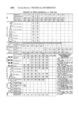
236    Section Eleven—TECHNICAL INFORMATION

                        WEIGHTS  OF  PIPING  MATERIALS—16"  PIPE  SIZE
              Schedule  No  10  20  30  40  60   80  100  120  140  160
       e      Wall Designation    Std  XS                             -'  i
       E      Thickness  -In  250  .312  375  .500  565  i  843  l.OSt  1.218  1  437  \ 5'«
               Pipe—Lbfv/Ft  42 t  52 4  626  828  1075  136 5  164 8  192 3  223 6  245  1
              \\uter-~ LW Ft  81  8  805  79  1  765  73 4  69 7  66  1  62.6  586  559
                                   201  265
               L.R.  90°  HI bow   4    4
                                   135  177
       «  (J-f  S  It  W  Klbow    2.5  2.5                            .
                                   too  132
               L.U  45  Kll>ow     1.7  1.7
                                 '  202  257
              '!><                 3.2  3.2
                                   650  774
               Lateral                 6.7              I         __.  ..     i
                                   78  102
               Reducer                 1.2
                                   44   58
              Cap                  1.8  1.8                 1
         Temperature  Range "V  to 260°  I 60-360 360-440 140-525 525-600 600-700 700-800 800-90C 5(00-1000  1 i  i
        859<-  I'hii'kni-* -In  Ui  2  24  3  3                           .| .  -  _
       f.  Magnesia  Lbs 'Ft  11.6  15.1  18.8  22.6  226             ——j.——
       *  Combma- Thickness  —In.               3Ji   4   4    4H   5
       O  tlon  Lbs  Ft                         32.0  37.2  37.2  43.6  51 4  58.4  I 65.7
                                                                     1
        Calcium  Thnkriobs- In.  1  1  U-i  1H  2  2,4  3  3'/ 2  4  4 4  5  I
        Silicate  FbVFt  4.40  4.40  6.65  6.65  9.02  11.5  14.1  16.8  19 7 22.7  25.1~| ~~~1
                         Oast  Iron          Steel
              I'tpssure Rating                                 SEE  GENERAL  NOTES
                         125  250  150  300  400  600  900  1500  2500  FOR MATERIALS
                                                                  NOT
                                                                     SHOWN
              Screwed or  120  233  108  261  310  442 ""559   All  weights are shown in bold
       FLANGES  Welding  Ne<k    116  257  308  492  564     type.  weight  of  stee!  pipe  is
                             1.5
                                              1.5
                                                  1.5
                                          1.5
                         1.5
                                     1.5
                                 1.5
              Slip-On
                                                               The
                                     1.5
                                 1.5
                                         1.5
                                              1.5
                                                  1.5
                                                              per linear foot.
                                 151  289  347   607           For  Boiler  Feed  Piping,  add
              Lap .fomt          1.5  1.5  1.5  1.5  1.5     the  weight  of  water  to  the
                                                              weight of steel pipe.
                         175  308  185  M8  455  603  809      The  pipe  covering  thick-
               Blind     1.5  1.5  1.5  1.5  1.5  1.5  1.5   nesses and  weights indicate  the
                                                             average  conditions  per  linear
      «i   x-i(l         501  826  656  958  1014  1402  1886  foot  and  include  all  allowances
          f«»M
       g g  ZJ  S  H. 90°  Klbow  5.5  5.8  5.5  5.8  6  6.3  6.7  for  wire,  cement,  canvas,  bands
                         701  1036  781  1058                and  paint.  The  listed  thick-
              L R  90" Klbow  7  7  7  7                     ness  of  combination  covering  is
                                                             the  sum  of  the  inner  and  the
           A  VT  K!b<>»  391  696  481  708  839  1212  1586  outer layer thickness.
                             4.6
      S 3  **«€          4.3     4 3  4.6  4.7  5  5           Pipe  covering  temperature
                                                                          ft
                                                                            guide
                                                                 are intended
                         746  1263  961  1404  1671  2128  3054  ranges  and  do  not  as constitute
                                                             only
              Tee        8.3  8.7  8.3  8.6  9  9.4  10      a  recommendation  for  speciric
                                                             thickness of materials.
              Flanged Bonnet  1254  2321  1315
        l-v~-f r t J ~t              2511  2694  3668          To  find  the  weight  of  cover-
        i"""-Ui /  Gate   8   9   5  7.1  7.5  7.9           ing  on Flanged Fittings,  Valves,
        ie~"'~1ir  ]  Flanged Bonnet                         or  Flanges,  multiply  the  weight
        I**W.«$L  /  Crlobc or Angle                         factor  (lightface  subscript)  by
                                                             the  weight per foot of  covering
              Flanged Bonnet  1166                           used on straight pipe.
              Check      10.5                                  •All  Flanged  Fitting,  Flanged
                                    _                        Valve and Flange weights include
              Pressure Seal                                  the  proportional  weight of  bolts
              Bonnet — Gate                                  or studs required to  make  up all
                                                             joints.
              Pressure Seal                                    **Cast  Iron  Valve  weights
              Bonnet^-Olobe                                  are  for  flanged  valves.  Steel
       j      *On«s Complete  31  76  31  83  114  152  199  Valve  weights  are  for  welding
                                                             end valves.
              Flanged Joint
   256   257   258   259   260   261   262   263   264   265   266