Page 263 - Estimators Piping Man Hour Manual
P. 263

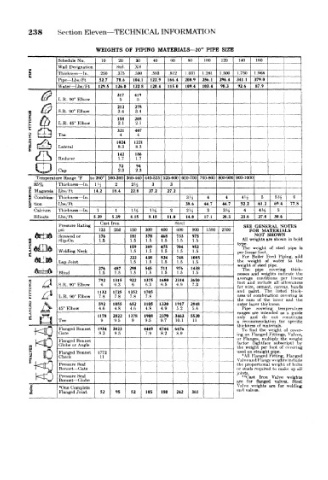
238    Section  Eleven—TECHNICAL INFORMATION

                        WEIGHTS  OF  PIPING  MATERIALS—20"  PIPE  SIZE
              Schedule No.  10  20  30  40  60   80  100  120  140  160    — 1
                                   xs
       s      Wai! Designation  .250  Htd.  .500  .593  .812  1 .031  1.281  1.500  1 .750  1 .968  1
              ThickmsM— In.
                              .375
              Pipe — Lbs/Ft  52.7  78.6  104.1  122.9  166.4  208.9  256.1  296.4  341 1  379.0
              Water— Lbs/Ft  129.5  126.0  122 8  120.4  1150  109.4  103.4  98.3  92.6  87.9
                              317  419
              L.R.  90" Elbow  5   5
                                                                   -  .1  j
                              212  278         j                     1
      !   &    L.R.  45° Elbow  158  208                                    —
                                   3.4
              S.R. 90° Elbow
                              3.4
                                   2.1
                              2.1
                              321  407                  j             -  4
              Tee              4   4
                                                                           .
                              1024  1221
              Lateral         8.3  8.3
                                               1
                              142  186
               Reducer        1.7  1.7
                                             . 1                        "  {  ~  '
                              72   94
              Cap             2.3  2.3
         Temperature Range "?  to 260°  260-360 360-440 440-525 >25-600  600-700 700-800 800-900 900-1000
                         l
        85%   Thickness— In.  \ i  2  2J-S  3  3
       9  »,
       Z  Magnesia  Lbs/Ft  14.2  18.4  22.8  27.2  27.2
       8  Oombina- Thickness — In.              3ii   4   4    4> 2  5  54  __.
                                                                            C
       fa tion  Lbs/Ft                          38.6  44.7  44.7  52.2  61 2  694
        Calcium  Thickness — In  i  1  Hi  IJ-i  2  2H  3  3'/ 2  4  4"' 2  5
        Silicate  LbR/Ft  539  5.39  8.15  8.15  11.0  14.0  17.1  20.3  236  27 0  30 6  —
                         Cast Iron           Steel
               Pressure Rating                                 SEE GENERAL  NOTES
               psi       125  250  150  300  400  600  900  1500 1  2500  f OR  MATERIAI S
                                                                     SHOWN
                                                                  NOT
               Screwed or  176   181  378  468  733  973       All v/eights are shown ni bok
       FLANGES  Welding Neck     159  389  475  704  952  _j_  type. hn« ar  foot  of  steel  pipe  k
                                      1.5
                                 1.5
                                          1.5
                                              1.5
                                                  1.5
               Slip-On
                         1.5
                                                               The weight
                                                  1.5
                                          1.5
                                      1.5
                                 1.5
                                              1.5
                                                              per
                                 222  438  524  748  1085      For Boiler  Fe< d  Piping, ad<
               Lap Joint         1.5  1.5  1.5  1.5  1.5      the  w pight  of  water  to  th«
                                                              weight of  steel pipe,
                         276  487  298  545  711  976  1438    The  pipe  covering  thick
               Blind     1.5  1.5  1.5  1.5  1.5  1.5  1.5    nesses and  weights  indicate  the
       8   jj,  S.R.  90° Elbow  792  1315  922  1375  1680  2314  3610  averagf ar d  conditions all  per  hneai
                                                                         allow, mcts
                                                                   include
                                                              foot
                                                  7.3
                                     6.3
                                              6.9
                                         6.5
                          6
                                  6
                             6.3
                                                                   cement, canvas,
                                                                wire,
                                                              for
                                                                            bands
       i  a    L.R.  90'  Flbow  1132  1725  1352  1705       and  paint  The  listed  tlni-k- is
                                                                         covering
                                                              ness -oi (ombmation
                                     7.8
                         7.8
                                 7.8
                             7.8
                                                                     the
                                                                       inner
       8   &             592  1055  652  1105  1330  1917  2848  the  su 11  of thickness,  ami  the
                                                              outer Itiy< r
       i ^     45" Elbow  4.6  4.8  4.6  4.8  4.9  5.2  5.4    Pl[W>  covering  tpmpeintnre
                                                                           a
                                                                            guide
                         1178  2022  1378  1908  2370  3463  5520  ranges are  intended  as con-titute
                                                                 f nd
                                                              onlv
                                                                    do
                                                                       not
               Tee        9  9.5  9  9.5  9.7  10.1  11       a  reto nmendah'm  for  si«-nfic
                                                              thickness of materials
               Flangt.d  Bonnet.  1934  3823  4449  4744  647b  To find  the  weight  of  < over-
               Gate      8.3  9.5    7.9  8.2  S.9            mg on Hanged Fittings, Valvi-s
                                                              or  Fiar ge-s,  multiply  the  weight
       .KO     Globe or Angle                                 factor dightface foot  of f«\umg
               Flanged
                   Bonnet
                                                                             by
                                                                       subscript)
                                                              the
                                                                    per
                                                                we ght
       I   ID  Flanged Bonnet  1772                      P    used or straight pipe.
                                                                      Fitting, f Umged
                                                               *U1 Hanged
               Check
                          11
       r                                                 L    \alvea id Flaiigi' weight" include
        ^O     Pressure Seal  1                              or the prc portional  weight  of bolts
                                                               >>tuda required
               Bonnet- Gate
                                                                       &> make up ull
        KO     Pressure Heal                                 joints. fo"  flanged  Valve  weights
                                                                   Iron
                                                               **Cast
               Bonnet—Globe
                                                                            Steel
                                                             are
                                                                       valves.
       i       Flanged Joint  52  95  52  105  180  242  361  ViiKe weights  are  for  weldmg
               *One Complete
                                                              end va. ves.
                                                         i
   258   259   260   261   262   263   264   265   266   267   268