
Page 260 - Estimators Piping Man Hour Manual
P. 260
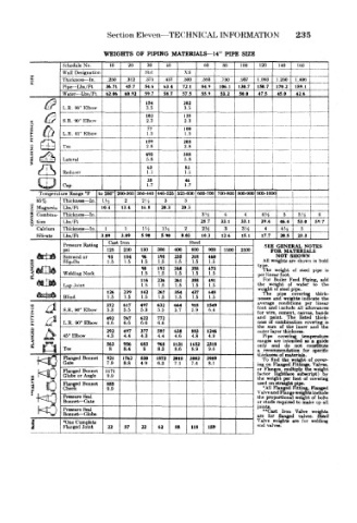
Section Eleven—TECHNICAL INFORMATION         235

                       WEIGHTS  OF PIPING  MATERIALS—14"  PIPE  SIZE
             Schedule No.  !0  20  30  40      60   80  100  120  140  160
             Wall Designation    IStrt    XS
     A.      Thickness — In.  .250  .312  .375  .437  .500  .593  .750  .937  1.093  1,250  1.406
     s
             Pipe— Lbs/Ft  36.71  45.7  54.6  63.4  72.1  84.9  106.1  130.7  150.7  170.2  189.1
             Water— Lbs/Ft  62.06  60.92  59.7  58.7  57.5  55.9  53.2  50.0  475  45.0  426
                                 154      202
             L.R.  90° Elbow     3.5      3.5
                                 102      135
             S.R. 90°  Elbow     2.3      2.3
                     _.                                    "  "  !
                                 77       100
             L.R.  45°  Elbow    1.5       .5     _
                                                         ' "    -._.
                                 159      203
             Tee                 2.8      2.8                               _
                                                           1
                                 495      588
             Lateral             5.8      5.8
                                 63       83
     1 Reducer                   1.1      1.1
                                 35       46
             Cap                 1.7      1.7
       Temperature Range °F  to  260° 260-360 360-440 140-525 525-600 600-700 700-800 800-90C 9oo-iooo{  i  '
       85%   Thickness— In. 1.4  2  24  3  3
     Z  Magnesia  Lbs/Ft  10.4  134  16.8  20.3  20.3
     *  Combina-  Thickness — In .             3,4  4    4   44   5   5.4  6
     ^  lion  Lbs/Ft                          28.7  33.1  33.1  39.4  46.4  53 0  59.7
       Calcium  Thickness— In.  1  1  14  14  2  24  3  34    4   4hz  5
       Silicate  Lbs/Ft  3.89  3.89  5.90  5.90  8.03  10.3  12.6  15.1  17.7  20.5  233  I
                        Cast Iron  r        Steel
             Pressure Rating                                  SEE  GENERAL  NOTES
             pel        125  250  150  300  400  600  900  1500  2500  FOR  MATERIALS
                                                                 NOT
                                                                    SHOWN
                                96
             Screwed or  93  184  1.5  195  235  318  460    All  weights  are shown  in  bold
      FLANGES  Welding Neck     1.5  192  240  358  473     type.  weight  of  steel  pipe  is
                        1.5
                                        1.5
                                            1.5
                            1.5
                                                1.5
             Slip-On
                                    1.5
                                90
                                                             The
                                                1.5
                                            1.5
                                    1.5
                                        1.5
                                                             For
                                                                Boiler
                                116  226  261  35S  491     per linear foot. Feed  Piping,  add
             Lap Joint          1.5  1.5  1.5  1.5  1.5     the  weight  of  water  to  the
                                                            weight of steel  pipe.
                        126  239  142  267  354  437  648    The  pipe  covering  thick-
             Blind      1.5  1.5  1.5  1.5  1.5  1.5  1.5   nesses  and  weights indicate  the
     8   /^l  S.R. 90° Elbow  372  617  497  632  664  918  1549  average  conditions all  per  linear
                                                            foot
                                                                        allowances
                                                               and include
                        5.3
                                                6.4
                                            5.9
                            5.5
                                        5.7
                                5.3
                                    5.5
                                                            for  wire,  cement,  canvas,  bands
                        492  767  622  772                  and  paint.  The  listed  thick-
     c   X«4  L.R. 90° Elbow  6.6  6.6  6.6  6.6            ness  of  combination  covering is
                                                            the  gum  of  the  inner  and  the
     Id  /^\            292  497  377  587  638  883  1246  outer layer thickness.
             45° Elbow  4.3  4.4  4.3  4.4  4.6  4,8  4.9    Pipe  covering  temperature
                                                                are
                                                                          guide
                                                                         a
     1                  563  956  683  968  1131  1652  2318  ranges and  intended  as constitute
        El   Tee        8   8.4  8  8.3  8.6  8.9  9.6      a  recommendation  for  specific
                                                            only
                                                                   do
                                                                     not
                                                            thickness of  material*.
             Flanged Bonnet  921  1762  830  1872  2018  3082  3989  To  find  the  weight  of  cover-
             Gate       7.9  8.8  4.9  6.3  7.1  7.4  8.1   ing on  Flanged  Fitting*, Valves,
             Flanged  Bonnet  1171                          or  Flanges,  multiply  toe  weight
                                                                            by
                                                                      subscript)
                                                                (lightfaee
                                                            factor
             Globe or Angle
                        9.9
     S o     Flanged  Bonnet  885                           the •All Fknged Fitting;,  covering
                                                                  per foot
                                                                       of
                                                              weight
                                                            used on straight pipe.
                                                                         Flanged
             Check
                        9.9
                                                            Valve and Flange weights include
             Pressure Seal                                  the  proportional weight of  bolt*
             Bonnet — Gate                                  or studs required to  make up ail
       HO    Pressure Seal                                  joints.  Iron  Valve  weight*
                                                             "Cast
             Bonnet — Globe
                                                            are  for  flanged  valves,  steel
     1       *One  Complete  22  57  22  62  88  118  159   Valve  weights  are  for  welding
                                                            end valves.
             Hanged Joint
                                _  J  ._