Page 264 - Estimators Piping Man Hour Manual
P. 264

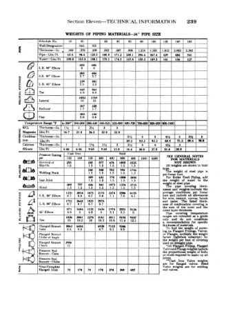
Section Eleven—TECHNICAL INFORMATION          239

                       WEIGHTS  OF  PIPING  MATERIALS—24"  PIPE  SIZE
                                                        100
                                                            120
                                          40
                                                   80
                                               60
                            20
                                      30
                        10
                                                                     160
     1       Schedule  No.  .250  Std.  .500  .562  .687  .968  1.218  1.531  1.812  2.062  2.343  _  _
                                                                 140
                                 XS
             Wall Designation
             Thickness— In.
                            .375
             Pipe— Lbs/Ft
                            94.6
                       63.4
                                     178.1
                                              165.8
                                         174.3
                                180.1
                                                                     127
                                                            141
             Water— Lbs/Ft  188.0  183.8  125.5  140.8  171.2  238.1  296.4  367.4  429  484  541
                                                   158.3
                                                                 134
                                                       149.3
                            458  606
             L.R. 90° Elbow  6   6
                            305  404
            S.R, 90" Elbow  3.7  3.7
                                                      1—
                            229  302
             L.R. 45° Elbow  2.5  2.5
                            445  563
             Tee            4.9  4.9
                            1482  1769
                                 10
     'o!     Reducer        167  220
             Lateral
                             10
                                 1.7
                            1.7
                            102  134
             Cap            2.8  2.8
       Temperature  Range °F  to 260°  'S60-360 360-440 440-525 525-600 600-700 700-800 800-900 900-1000
             Thickness— In.  2  2M   3    3
                      l'/2
     £  Magnesia  Lbs/Ft  16.7  21.8  26.8  32.0  32.0
                                                             1
     M  Combina- Thickness — In.              314   4    4   4 A  5   SH   6
     o  tion  Lbs/Ft                          45.2  52.2  52.2  60.8  71.2  80.4  90.0
      Calcium  Thickness — In.  1  1  m  IJi  2  V4  3   4   4H   5
      Silicate  Lba/Ft  6.44  6.44  9.65  9.65  13.0  16.4  20.0  27 .5  31.4  3S.5
                       (.last Iron         Steel
             Pressure Rating                                 SEE  GENERAL  NOTES
             psi       125  250  150  300  400  600  900  1500  2500  FOR  MATERIALS
             Screwed or  255   245  577  676  1055  1823        NOT  SHOWN
             Slip-On   1.5      1.5  1.5  1.5  1.5  1.5      All weights are shown in bolt
     2  r-H,
                               248  580  702  998  1793     typ?-
                                                                weight
                                                             The
             Welding Neck       1.5  1.5  1.5  1.5  1.5     per linear foot.  ol  steel  pipe  IB
                               309  631  770  1080  2058     For  Boiler  Feed  Piping,  adc
             Lap Joint          1.5  1.5  1.5  1.5  1.5     the  weight  of  water  to  the
                       405  757  446  841  1073  1354  2715  weight of Hteel pipe.
                                                                 pipe
                                                                    covering
                                                             The
             Blind     1.5  1.5  1.5  1.5  1.5  1.5  1.5    nesses  and weights indicate thkk-
                                                                           the
     at  X j j         1231  2014  1671  2174  2474  3506  6155  average  conditions  per  linear
     O  £,£«  S.R. 90° Elbow  6.7  6.8  6.7  6.8  7.1  7.6  8.1  foot  and include  all  allowances
                                                            for  wirCj cement,  canvas,  bands
                       1711  2644  1821  2874               and  paint.  The  listed  thick-
             L.R. 90° Elbow  8.7  8.7  8.7  8.7
     Sfe  fl*P»                                             ness  of  combination  covering  is
                                                            the  sum  of  the  inner  and  the
                       871  1604  1121  1634  1974  2831  5124  outer layer thickness.
     1 £     45° Elbow  4.8  5  4.8  5  5.1  5.5  6          Pipe  covering  tewpernture
                                                            ranges  are intended  as  a guide
                       1836  3061  2276  3161  3811  5184  9387
             Te«       10  10.2  10  10.2  10.6  11.4  12.1  only  and  do  not  constitute
                                                            a  reeonuneadation  for  specific
             Flanged Bonnet  3062  6484  6920  7122  9246   thickness of materials.
             Gate      8.5  9.8    8.7  9.1  9.9             To  find  the  weight  of  cover-
                                                            ing on Flanged Fittings, Valves
             Flanged Bonnet                                 or  Flanges,  multiply  the weigh!
             Globe or Angle                                 factor  (lightface  subscript)  by
                                                            the  weight  per foot  of covering
     |   0   Flanged Bonnet  2956                           used on straight pipe.  Flanged
                       12
             Check
                                                             •All Ftanged Fitting,
             Pressure Seal                                  Valve and Flange weights include
                                                              proportional
                                                            the
                                                                     weight of bolts
             Bonnet — Gate                                  or studs required to nuke up  aJ
      NO     Pressure Seal                                  joints.
             Bonnet— Globe                                   **Cast  Iron  Valve  weight)
                                                            are  for  flanged  valves.  Staw
                Complete
             'One
     i      Flanged Joint  71  174  71  174  274  360  687  Valve  weights  tan  for  welding
                                                            end valves.
   259   260   261   262   263   264   265   266   267   268   269