
Page 262 - Estimators Piping Man Hour Manual
P. 262
Section Eleven—TECHNICAL INFORMATION 237
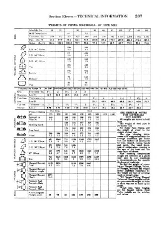
WEIGHTS OF PIPING MATERIALS- 18" PIPE SIZE
Schedule No 10 .. -I' ) 40 W) 80 i 100 120 140 i IrtO ™
„
a Wall Designatiot •r>o M.I V - 1 :»i.5
5 I'hu'knes., In 312 ,17 'i 437 ">00 T.'iO «)37 1 !5li I 375 1 .%<! 1 7»l
Pipe Lbk, 1 t 474 590 706 82 1 935 104 8 138 2 170 8 2080 244 1 2742 308 5
\Vatcr Lbs/ Ft 1043 1028 101 2 99.'> 98 4 •)7 0 42 7 88 .1 837 79 2 753 71 0
256 338
L H <XT Elbow 4 5 4.o
I 171 225
S H 90° Elhow 2.8 .2.S
128 168
I,.R, 45" Kllmw 1.9
_ J , . _
258 328 :
Tee 3.t> 3.H
7<>8 984
Lateral 7.5 7.5
l 94 123
& Reducer 1.3 1.3
57 75 —
Cap 2.1 •2.1
j
Temperat ire Range °F tio2tW 2 (10-3tiO 3«0-44<) 440-525 525-iiOO 1100-700 "00-800 800-900 '.WO- 100!)
j -,
ThirkneKs— In l'<2 2 2'j 3 3
'J ,,
2 Magnesia Lbs H 12.9 16 0 20 8 25 0 250
1
* Combina- Thickness — In. 3 j 54 ^~ fi '
0 tmn Lbs 'Ft 35 3 40 9 40.9 480 56.3 640 717
< 'ali-mm Thickne>is - In 1 1 1 ! 2 1' _• 2 2'i 3 34 4 4'* 5
Silicate Lbh Ft 4.91 491 7.40 740 10 0 12 7 156 18.6 21.7 259 28 2
Cast Iron '•Steel
Pressure Rating SEE GENERAL NOTES
psi 125 250 150 300 400 fiOO 900 1500 2.">00 FOR MATERIALS
Screwed or 140 140 331 380 573 797 All weights are shown in bold
NOT
SHOWN
FLANGES Welding Neck 128 316 377 569 786 type. weight of steel pipe ia
1.5
1.5
1.5
1.5
1.5
1.5
Shp-On
The
176 365 428 584 850 per linear foot. Feed Piping, add
For
Boiler
Lap Joint 1.5 1.5 1.5 1.5 1.5 the weight of water to the
weight of steel pipe.
210 396 229 441 572 762 1152
pipe
covering
thiek-
The
Blind 1.5 1.5 1.5 1.5 1.5 1.5 1.5 nesses and weighte indicate the
s s *w" S.R. 90° Elbow 621 1060 711 1126 1340 1793 2817 7 average conditions per linear
/I
allowances
and include all
foot
5.8
ti
6.6
6.2
5.8
6
The
and
881 1350 941 1426 for wire, cement, canvas, bands
paint.
thick-
listed
L R. W Klbow 7.4 7.4 7.4 7.4 ness of combination covering ia
the sura of the inner »nd the
A
i z *y* 45" Rlbow 461 870 521 90J 1040 1543 5 2252 outer layer thickness. temperature
4.4
4.4
4.7
4.8
4.7
5.2
Pipe
covering
ranges are intended as a guide
921 1625 1010 1602 1909 2640 4327
Tee 8.6 9 8.6 9 9 3 9.9 10.5 only and do not constitute
a recommendation for specific
Flanged Bonnet 1629 2578 3189 3580 5647 thickness of materials. bl cover-
weight
find
the
To
Gate 8.2 9.3 7.5 7.8 8.4
ing on Flanged Fittings, Valves,
or Flanges, multiply Use weight
S Flanged Bonnet factor (lightface subscript) by
Globe or Angle
of
per foot
covering
weight
the
1 0 Flanged Bonnet 137t used on straight pipe.
10.5
•All Flanged Fitting, Hanged
Check
'•HO Pressure Seal Valve and Flange weights include
proportional weight of bolts
the
Bonnet- — Gate
or studs required to make up all
HO Pressure Seal joints. Iron Valve weights
**Cast
Bonnet— Globe
are for flanged valveg. Steel
3 *One Complete Valve weighte are for welding
1 Flanged Joint 41 93 41 101 139 193 299 end valves.