
Page 88 - Facility Piping Systems Handbook for Industrial, Commercial, and Healthcare Facilities
P. 88
PIPING
2.38 CHAPTER TWO
3. Magnetic testing. First, an electrical current is passed through a pipe to induce a mag-
netic field in the pipe. Colored metal chips are then applied to a pipe joint. Since the
magnetic field is strongest where the voids and defects occur, an accumulation of them
indicates a flaw. Since stainless steel is nonmagnetic, this method is not used for lines
made of this material.
4. Ultrasonic testing. This method uses an ultrasound generator and a screen to display
reflected images from the weld. The most difficult part of this technique is to find well-
trained and qualified operators. This is a costly procedure and not used for drainage lines.
5. X-ray testing. This technique uses an x-ray picture of the weld to disclose defects. This
is the best of the various types but the most costly. Due to its cost, it is not used for
drainage lines. This is the most commonly used when a record of the weld is required,
but this is rarely required for drainage piping.
FLANGED
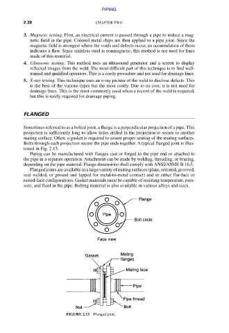
Sometimes referred to as a bolted joint, a flange is a perpendicular projection of a pipe. This
projection is sufficiently long to allow holes drilled in the projection to secure to another
mating surface. Often, a gasket is required to assure proper seating of the mating surfaces.
Bolts through each projection secure the pipe ends together. A typical flanged joint is illus-
trated in Fig. 2.13.
Piping can be manufactured with flanges cast or forged to the pipe end or attached to
the pipe in a separate operation. Attachment can be made by welding, threading, or brazing,
depending on the pipe material. Flange dimensions shall comply with ANSI/ASME B 16.5.
Flanged joints are available in a large variety of mating surfaces (plain, serrated, grooved,
seal welded, or ground and lapped for metal-to-metal contact) and in either flat-face or
raised-face configurations. Gasket materials must be capable of resisting temperature, pres-
sure, and fluid in the pipe. Bolting material is also available in various alloys and sizes.
FIGURE 2.13 Flanged joint.
Downloaded from Digital Engineering Library @ McGraw-Hill (www.accessengineeringlibrary.com)
Copyright © 2009 The McGraw-Hill Companies. All rights reserved.
Any use is subject to the Terms of Use as given at the website.