
Page 257 - Failure Analysis Case Studies II
P. 257
242
Fig. 1. Schematic of hold-down and bolts (numbered 14).
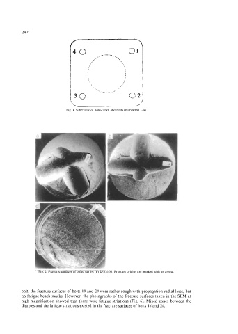
Fig. 2. Fracture surfaces of bolts. (a) l#; (b) 2#; (c) 3#. Fracture origins are marked with an arrow.
bolt, the fracture surfaces of bolts 1# and 2# were rather rough with propagation radial lines, but
no fatigue beach marks. However, the photographs of the fracture surfaces taken in the SEM at
high magnification showed that there were fatigue striations (Fig. 6). Mixed zones between the
dimples and the fatigue striations existed in the fracture surfaces of bolts 1# and 2#.