
Page 252 - Failure Analysis Case Studies II
P. 252
23 7
-05
--I
rhread Root
location
Fatigue Crack
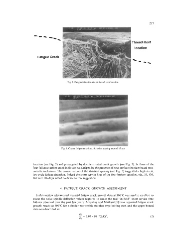
Fig. 2. Fatigue initiation site at thread root location
Fig. 3. Coarse fatigue striations. Striation spacing around 15 pm
location (see Fig. 2) and propagated by ductile striated crack growth (see Fig. 3). In three of the
four failures surface crack initiation was helped by the presence of near surface titanium based non-
metallic inclusions. The coarse nature of the striation spacing (see Fig. 3) suggested a high stress,
low cycle fatigue situation. Indeed the short service lives of the four broken spindles, viz., 33, 136,
167 and 3 16 days added credence to this suggestion.
4. FATIGUE CRACK GROWTH ASSESSMENT
In this section relevant real material fatigue crack growth data at 300°C was used in an effort to
assess the valve spindle deflection values required to cause the real “in field” short service time
failures observed over the past few years. Amzallag and Maillard [l] have reported fatigue crack
growth results at 300°C for a similar martensitic stainless type bolting steel and the upper bound
data was described as:
da
- = 1.05 x 10⁻⁶(AK)2,
dn (2)