
Page 251 - Failure Analysis Case Studies II
P. 251
236
SPRING ff"i 3 0.25MM
n
CLEARANCE
\M
HOUSING 11 ,-
I ll&i
POSITIONB B
VALVE
SPINDLE
I STEAM '
TO
TURBINE
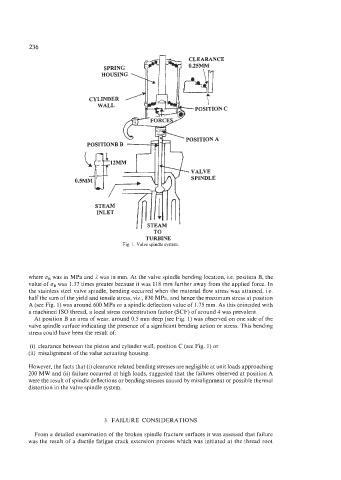
Fig. 1. Valve spindle system.
where uB was in MPa and 1 was in mm. At the valve spindle bending location, Le. position B, the
value of uB was 1.37 times greater because it was 118 mm further away from the applied force. In
the stainless steel valve spindle, bending occurred when the material flow stress was attained, Le.
half the sum of the yield and tensile stress, viz., 830 MPa, and hence the maximum stress at position
A (see Fig. I) was around 600 MPa or a spindle deflection value of 1.75 mm. As this coincided with
a machined IS0 thread, a local stress concentration factor (SCF) of around 4 was prevalent.
At position B an area of wear, around 0.5 mm deep (see Fig. 1) was observed on one side of the
valve spindle surface indicating the presence of a significant bending action or stress. This bending
stress could have been the result of:
(i) clearance between the piston and cylinder wall, position C (see Fig. 1) or
(ii) misalignment of the value actuating housing.
However, the facts that (i) clearance related bending stresses are negligible at unit loads approaching
200 MW and (ii) failure occurred at high loads, suggested that the failures observed at position A
were the result of spindle deflections or bending stresses caused by misalignment or possible thermal
distortion in the valve spindle system.
3. FAILURE CONSIDERATIONS
From a detailed examination of the broken spindle fracture surfaces it was assessed that failure
was the result of a ductile fatigue crack extension process which was initiated at the thread root