Page 248 - Failure Analysis Case Studies II
P. 248

233


                                          8.0 -

                                          7.2-
                                                  - Axial coil       j
                                          6.4 -   ........  Transverse coil   i
                                      8   5.6 -                      1
                                      2
                                      .a
                                      B   4.8 -
                                                                     jl
                                          4.0 -
                                          3.2 -
                                          2.4 -

                                          1.6-
                                          0.8 -
                                                     hi
                                                           ..._
                                                A   .i . .._..___._..:   ..'d  :.
                                                          3,
                                                           *
                                            0-   I   I   I   I   I   I   I   I   I  1
                                                        (a) 1/2 inch flange size


                                           2.0 -

                                           1.8 -
                                                     Axial coil
                                           1.6 -   . ... . . . .  Transverse coil

                                           1.4 -
                                           1.2 -

                                           1.0 -


                                                         (b) 1 inch flange size
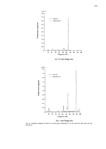
                           Fig.  10. Frequency response of  node 33  showing peak displacement for the transverse and axial coil con-
                           figurations.
   243   244   245   246   247   248   249   250   251   252   253