
Page 244 - Failure Analysis Case Studies II
P. 244
229
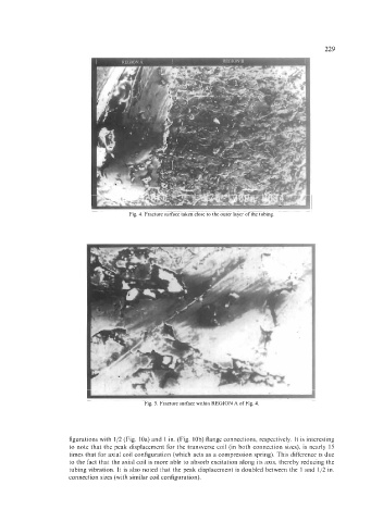
Fig. 4. Fracture surface taken close to the outer layer of the tubing
Fig. 5. Fracture surface within REGION A of Fig. 4.
figurations with 1/2 (Fig. loa) and 1 in. (Fig. lob) flange connections, respectively. It is interesting
to note that the peak displacement for the transverse coil (in both connection sizes), is nearly 15
times that for axial coil configuration (which acts as a compression spring). This difference is due
to the fact that the axial coil is more able to absorb excitation along its axis, thereby reducing the
tubing vibration. It is also noted that the peak displacement is doubled between the 1 and 1/2 in.
connection sizes (with similar coil configuration).