
Page 247 - Failure Analysis Case Studies II
P. 247
232
Mode 1
Mode
\
- undeformed shape
.......... deformed shape
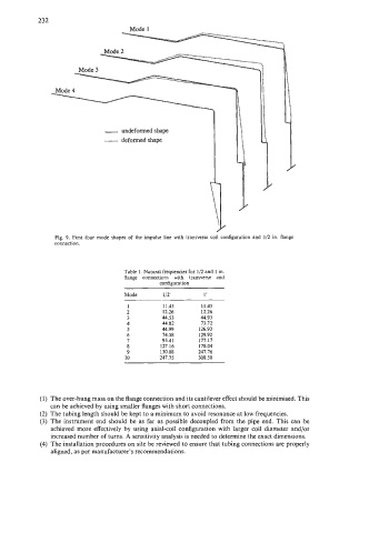
Fig. 9. First four mode shapes of the impulse line with transverse coil configuration and 1/2 in. flange
connection.
Table 1. Natural frequencies for 1/2 and 1 in.
flange connections with transverse coil
configuration
Mode 1 /2’ 1’
1 11.45 1 1.45
2 12.26 12.26
3 44.53 44.93
4 44.82 73.72
5 44.99 126.93
6 74.58 129.92
7 95.41 177.17
8 127.16 178.04
9 130.08 247.76
10 247.75 308.50
(1) The over-hung mass on the flange connection and its cantilever effect should be minimised. This
can be achieved by using smaller flanges with short connections.
(2) The tubing length should be kept to a minimum to avoid resonance at low frequencies.
(3) The instrument end should be as far as possible decoupled from the pipe end. This can be
achieved more effectively by using axial-coil configuration with larger coil diameter and/or
increased number of turns. A sensitivity analysis is needed to determine the exact dimensions.
(4) The installation procedures on site be reviewed to ensure that tubing connections are properly
aligned, as per manufacturer’s recommendations.