
Page 243 - Failure Analysis Case Studies II
P. 243
228
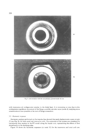
Fig. 3. End connector with the factured piece jammed inside the nut
with transverse-coil configuration (similar to the failed line). It is interesting to note that in this
configuration significant movement of the flange assembly can also occur (mode 4), implying stress
concentration is also possible at the root of flange connection.
3.3. Harmonic response
Harmonic analysis performed on the impulse line showed that peak displacements occur at node
33 (see Fig. S), for both axial and transverse coils. The excitation of the system was simulated by
introducing base motion in the FE model along the header axis, representing the effects of flow
disturbances in the discharge pipe.
Figure 10 shows the harmonic responses (at node 33) for the transverse and axial coil con-