
Page 254 - Failure Analysis Case Studies II
P. 254
239
VALVE
SPINDLE
DEFLECTION
(MM)
UNIT POWER 0
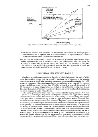
Fig. 6. Schematic of spindle deflection versus unit power and calculated cycles to fatigue failure.
(iii) the failures occurred over very short and unacceptable service durations; and large spindle
deflections occurred at high unit loads as failures occurred in this regime and could only have
come from out of alignment of the actuating mechanism.
As a result Fig. 6 is semi-schematic in nature and illustrates the spindle bending and spindle fatigue
breakage regions together with the notional increase in valve spindle deflection with unit power and
the number of fatigue cycles required to cause spindle failure. It is clear that reducing the spindle
deflection increased the working life of the spindle; indeed at deflections approaching 0.6 mm it was
predicted that the spindle life was 21,200 cycles or almost 12 years.
5. DISCUSSION AND RECOMMENDATIONS
It has been reasonably demonstrated that the series of spindle failures were the result of a high
stress, ductile fatigue process that was caused by significant out-of-alignment of the actuating
mechanism during service. During an outage, an exercise was conducted to determine the “cold”
amount of misalignment of an actuating mechanism where a fatigue failure occurred. The measured
amount was 0.38 mm which was more than 40% of the lower end valve spindle deflection level of
0.9 mm required to cause fatigue failure. As such, it is not difficult to envisage that thermal
distortions during the hot “on-load” excursion could easily account for spindle deflections attaining
the critical range necessary for fatigue failure.
Such a recurring failure in a critical plant component needed to be urgently addressed in an effort
to obviate or at least mitigate the problem. In the present instance it was suggested that the high
stress situation at the spindle threaded location be reduced by two actions; firstly, changing the
thread profile to a rounded thread (e.g. NF000-032 type thread) which had an associated stress
concentration factor which was about 25% lower than the present square IS0 thread and secondly
by introducing significant compressive stresses (which need to be overcome before fatigue can occur)
by shot peening. The influence of these actions on the valve spindle deflection-time to fatigue failure
relationship is illustrated in Fig. 7. From Fig. 7 it can be seen that both shot peening and re-profiling
the thread significantly increased the valve spindle life at spindle deflection levels of around 1 mm.
Indeed at 0.9 mm spindle deflection the spindle service life was increased from less than one year to
around 8 years. The service temperature in the region of valve spindle failure was estimated to be
around 300°C and it is known that thermal relaxation of the compressive stresses can occur at high
temperature. However, recently Gauchet et al. [2] have reported encouraging results where significant