
Page 382 - Failure Analysis Case Studies II
P. 382
367
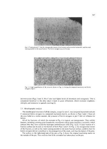
Fig. 2. Fractured pin C. Note the intergranular nature of the fracture surface on the bottom left, and the crack
running parallel to the main fracture. The ferrite stringers can also be seen.
Fig. 3. A high magnification of the structure shown in Fig. 2, showing the tempered martensite and ferrite
stringers of pin C.
microstructure (Figs 2 and 3). Pin C also had higher levels of chromium and manganese. This is
considered beneficial to the alloy since it leads to grain refinement, which increases toughness,
strength, and resistance to quench cracking [ 11.
2.3. Metallographic analysis
The metallurgical structure of all the samples, except for pin C, was tempered martensite and pin
C contained ferrite stringers in a tempered martensite matrix, as shown in Figs 2 and 3. Since all
the pins failed in a similar manner, the presence of ferrite stringers in pin C did not influence its
failure.
All of the fractures, of which the example in Fig. 4 is typical, are intergranular. They exhibit
features, including yawning grain boundaries, micropores and no grain boundary corrosion, which
indicate that they were caused by hydrogen embrittlement (HE) (Fig. 5) [2]. A small section of a
fracture surface can be seen at the bottom of both Figs 2 and 4. In Fig. 2, the intergranular nature
of the fracture, as well as the crack running parallel to the main fracture surface, confirms that the
ferrite stringers did not contribute to the propagation of the crack, and thus the failure of the pins.
The surface on the right-hand side of the pin in Fig. 4 shows the original machining marks on
the outside of the pin. This confirms that little corrosion had taken place on the pin.