
Page 546 - Fair, Geyer, and Okun's Water and wastewater engineering : water supply and wastewater removal
P. 546
JWCL344_ch14_500-554.qxd 8/7/10 8:56 PM Page 504
504 Chapter 14 Design of Sewer Systems
A or 6 A
1 2 3 4 5
d
Plan
5 or 6
b
1 2 3 4
a c
Cellar
Cellar
Cellar Water main
Rock
Profile
Drop
1. Combined through 2. Through manhole with
and terminal manhole no change in grade
3. Through and
drop manhole
Water
Overflow
supply
Syphon
4. Through manhole 5. Terminal manhole 6. Automatic flush tank
with change in grade about to discharge
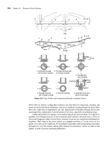
Figure 14.5 Plan, Profile, and Constructional Details of Sanitary Sewers.
600 ft (183 m). Sewers so large that workmen can enter them for inspection, cleaning, and
repair are freed from these restrictions, and access manholes are placed quite far apart either
above the center line or tangential to one side. Introduction of flexible cleaning devices has
encouraged the construction of curved sewers of all sizes, especially in residential areas.
A plan and profile of a sanitary sewer and its laterals are shown in Figs. 14.5 and 14.6,
together with enlarged sections of sewer trenches and manholes. On short runs ( 150 ft or
46 m) and temporary stubs of sewer lines, terminal cleanouts are sometimes substituted for
manholes. They slope to the street surface in a straight run from a Y in the sewer or in a
gentle curve that can be rodded out. To keep depths reasonably small and pumping reasonably
infrequent in very flat country and in other unusual circumstances, sewers are laid on flat
grades, in spite of greater operating difficulties.