
Page 563 - Fair, Geyer, and Okun's Water and wastewater engineering : water supply and wastewater removal
P. 563
JWCL344_ch14_500-554.qxd 8/7/10 8:56 PM Page 521
14.9 Layout and Hydraulic Design in Sanitary Sewerage 521
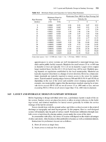
Table 14.2 Minimum Slopes and Capacities for Various Pipe Diameters
Wastewater Flow, MGD for Pipe Flowing Full
Minimum Slope for
Pipe Diameter Pipe Velocity of Velocity, ft/s
(Inches) 2 ft/s 8 ft/s 2 3 4 8
6 0.0060 0.075 0.26 0.36 0.47 0.91
8 0.0038 0.045 0.48 0.69 0.91 1.76
10 0.0030 0.035 0.72 1.04 1.37 2.54
12 0.0022 0.026 1.04 1.46 1.94 3.51
15 0.0015 0.020 1.69 2.47 3.25 5.84
18 0.0012 0.016 2.41 3.45 4.42 9.43
21 0.0010 0.013 3.38 4.94 6.37 12.35
24 0.00078 0.011 4.10 6.24 8.13 15.28
27 0.00065 0.0095 5.20 7.80 10.08 18.85
30 0.00058 0.0080 6.50 9.75 13.00 24.05
36 0.00045 0.0060 9.75 14.63 18.20 37.05
42 0.00038 0.0050 13.00 19.50 25.36 48.10
48 0.00032 0.0045 16.25 24.70 31.85 59.80
54 0.00026 0.0039 20.80 31.85 39.65 84.50
Conversion factors: 1 ft/s 0.3048 m/s; 1 inch 1 in. 25.4 mm; 1 MGD 43.8 L/s.
appurtenances in sewer systems are well documented in municipal design stan-
dards and/or public facility manuals. Manholes for small sewers (24 in. or 600 mm
in diameter or less) are typically 4 ft (1.22 m) in diameter. Larger sewers require
larger manhole bases, but the 4-ft (1.22-m) barrel may still be used. Manhole spac-
ing depends on regulations established by the local municipality. Manholes are
typically required when there is a change of sewer direction. However, certain min-
imum standards are typically required to ensure access to the sewer for mainte-
nance. Typical manhole spacing ranges between 300 and 600 ft (91.44 and 182.88 m)
depending on the size of the sewer and available sewer cleaning equipment. For
example, one municipality requires that the maximum manhole spacing be at inter-
vals not to exceed 400 ft (120 m) on all sewers 15 in. (400 mm) or less, and not
exceeding 500 ft (150 m) on all sewers larger than 15 in. (400 mm) in diameter.
14.9 LAYOUT AND HYDRAULIC DESIGN IN SANITARY SEWERAGE
Before beginning to design individual sewer runs, a preliminary layout is made of the en-
tire system. Sanitary sewers are placed in streets or alleys in proper reference to the build-
ings served, and terminal manholes for lateral sewers generally lie within the service
frontage of the last lot sewered.
Sewers should slope with the ground surface and follow as direct a route to the point of
discharge as topography and street layout permit. To this purpose, flow in a well-designed
system will normally take the path of surface runoff. Stormwater infiltration through man-
hole covers is kept down by placing sanitary sewers under the crown of the street.
In communities with alleys, the choice of location will depend on the relative advantages
of alleys and streets. Alley location is often preferable in business as well as residential districts.
Instructions for preliminary layouts are as follows:
1. Show all sewers as single lines.
2. Insert arrows to indicate flow direction.