
Page 210 - Fiber Fracture
P. 210
STRENGTH AND FRACTURE OF METALLIC FILAMENTS 195
0 100 200 300 [GPal
Young’s modulus
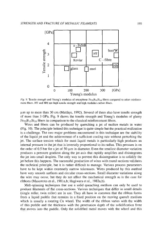
Fig. 9. Tensile strength and Young’s modulus of amorphous Fe7sBlsSilo fibers compared to other reinforce-
ment fibers. HT and HM are high tensile strength and high modulus carbon fibers.
km up to more than 30 cm (Matthys, 1992). Several of them also have tensile strength
of more than 3 GPa. Fig. 9 shows the tensile strength and Young’s modulus of glassy
Fe75B ,sSilO fibers in comparison to the classical reinforcement fibers.
Wires and fibers can be produced by quenching a jet of molten metals in water
(Fig. 10). The principle behind this technique is quite simple but the practical realization
is a challenge. The two major problems encountered in this technique are the stability
of the liquid jet and the achievement of a sufficient cooling rate without perturbing the
jet. The surface tension which for most liquid metals is particularly high produces an
internal pressure in the jet that is inversely proportional to its radius. This pressure is on
the order of 0.5 bar for a jet of 50 km in diameter. Even the smallest diameter variation
produces a pressure gradient along the jet axis that rapidly amplifies and disintegrates
the jet into small droplets. The only way to prevent this disintegration is to solidify the
jet before this happens. The successful production of wires with round sections validates
the technical principle, but it is rather difficult to manage. Various process parameters
have to be kept within extremely narrow tolerances. Wires produced by this method
have very smooth surfaces and circular cross-sections. Small diameter variations along
the wire may occur, but they do not affect the mechanical strength as is the case for
ribbons (Masumoto et al., 1981a,b; Hagiwara et al., 1982a,b).
Melt-spinning techniques that use a solid quenching medium can only be used to
produce filaments of flat cross-sections. Various techniques that differ in small details
(single roller, twin roller) are in use. They all have in common that the ribbon forms
from a liquid puddle that remains in a fixed position on the moving quench medium
which is usually a rotating Cu wheel. The width of the ribbon varies with the width
of this puddle and the thickness with the penetration depth of the solidification front
that moves into the puddle. Only the solidified metal moves with the wheel and this