
Page 18 - Finite Element Modeling and Simulations with ANSYS Workbench
P. 18
Introduction 3
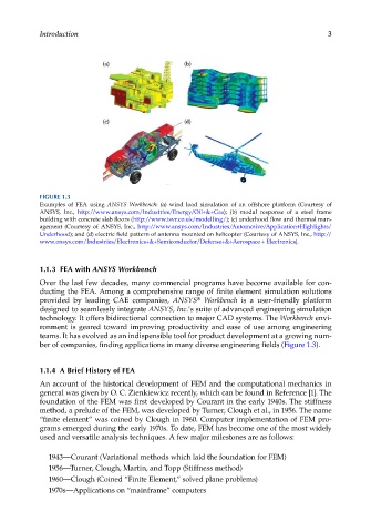
FIGURE 1.3
Examples of FEA using ANSYS Workbench: (a) wind load simulation of an offshore platform (Courtesy of
ANSYS, Inc., http://www.ansys.com/Industries/Energy/Oil+&+Gas); (b) modal response of a steel frame
building with concrete slab floors (http://www.isvr.co.uk/modelling/); (c) underhood flow and thermal man-
agement (Courtesy of ANSYS, Inc., http://www.ansys.com/Industries/Automotive/Application+Highlights/
Underhood); and (d) electric field pattern of antenna mounted on helicopter (Courtesy of ANSYS, Inc., http://
www.ansys.com/Industries/Electronics+&+Semiconductor/Defense+&+Aerospace + Electronics).
1.1.3 FEA with ANSYS Workbench
Over the last few decades, many commercial programs have become available for con-
ducting the FEA. Among a comprehensive range of finite element simulation solutions
provided by leading CAE companies, ANSYS Workbench is a user-friendly platform
®
designed to seamlessly integrate ANSYS, Inc.’s suite of advanced engineering simulation
technology. It offers bidirectional connection to major CAD systems. The Workbench envi-
ronment is geared toward improving productivity and ease of use among engineering
teams. It has evolved as an indispensible tool for product development at a growing num-
ber of companies, finding applications in many diverse engineering fields (Figure 1.3).
1.1.4 A Brief History of FEA
An account of the historical development of FEM and the computational mechanics in
general was given by O. C. Zienkiewicz recently, which can be found in Reference [1]. The
foundation of the FEM was first developed by Courant in the early 1940s. The stiffness
method, a prelude of the FEM, was developed by Turner, Clough et al., in 1956. The name
“finite element” was coined by Clough in 1960. Computer implementation of FEM pro-
grams emerged during the early 1970s. To date, FEM has become one of the most widely
used and versatile analysis techniques. A few major milestones are as follows:
1943—Courant (Variational methods which laid the foundation for FEM)
1956—Turner, Clough, Martin, and Topp (Stiffness method)
1960—Clough (Coined “Finite Element,” solved plane problems)
1970s—Applications on “mainframe” computers