
Page 21 - Finite Element Modeling and Simulations with ANSYS Workbench
P. 21
6 Finite Element Modeling and Simulation with ANSYS Workbench
or,
ku = f (1.3)
where
k = element stiffness matrix
u = element nodal displacement vector
f = element nodal force vector
From the derivation, we see that the first equation in Equation 1.2 represents the equilib-
rium of forces at node i, while the second equation in Equation 1.2 represents the equilib-
rium of forces at node j. Note also that k is symmetric. Is k singular or nonsingular? That
is, can we solve the equation in Equation 1.2? If not, why?
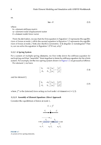
1.2.2 A Spring System
For a system of multiple spring elements, we first write down the stiffness equation for
each spring and then “assemble” them together to form the stiffness equation for the whole
system. For example, for the two-spring system shown in Figure 1.7, we proceed as follows:
For element 1, we have
k 1 − k 1 u 1 f 1
1
− = 1 (1.4)
k 1 k 1 u 2 f 2
and for element 2,
2
k 2 − k 2 u 2 f 1
− = 2 (1.5)
k 2 k 2 u 3 f 2
m
where f i is the (internal) force acting on local node i of element m (i = 1, 2).
1.2.2.1 Assembly of Element Equations: Direct Approach
Consider the equilibrium of forces at node 1,
F 1 = 1
f 1
F 1 1 f 1 1
x
k 1 k 2
1 2 3
u , F 1 u , F 2 u , F
3
1
2
3
FIGURE 1.7
A system of two spring elements.