
Page 20 - Finite Element Modeling and Simulations with ANSYS Workbench
P. 20
Introduction 5
1.2.1 One Spring Element
For the single element shown in Figure 1.5, we have:
Two nodes i, j
Nodal displacements u i , u j (m, mm)
Nodal forces f i , f j (Newton)
Spring constant (stiffness) k (N/m, N/mm)
Relationship between spring force F and elongation Δ is shown in Figure 1.6.
In the linear portion of the curve shown in Figure 1.6, we have
F = kΔ, with Δ = u − u i (1.1)
j
where k = F/Δ(>0) is the stiffness of the spring (the force needed to produce a unit stretch).
Consider the equilibrium of forces for the spring. At node i, we have
f = −F = −k(u − u) = ku − ku j
i
i
i
j
f i i F
and at node j
f = F = k(u − u) = −ku + ku j
j
i
i
j
F j f
j
In matrix form,
k − k f i
u i
− k k = (1.2)
u j
f j
x
i j
f i u i k u j f j
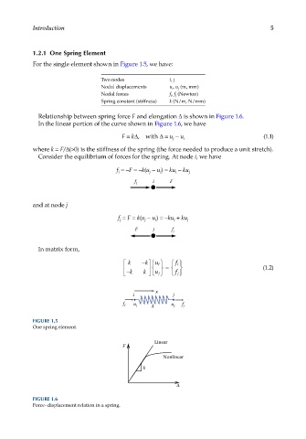
FIGURE 1.5
One spring element.
Linear
F
Nonlinear
k
∆
FIGURE 1.6
Force–displacement relation in a spring.