
Page 22 - Finite Element Modeling and Simulations with ANSYS Workbench
P. 22
Introduction 7
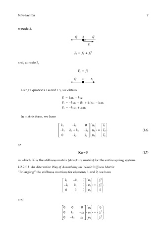
at node 2,
f 2 1 2 f 1 2
F 2
F 2 = f 2 + f 1 2
1
and, at node 3,
F 3 = f 2 2
f 2 2 3 F 3
Using Equations 1.4 and 1.5, we obtain
F 1 = k u 1 − k u 2
1
1
F 2 =− k u 1 + ( k 1 + ku 2 − ku
)
2
1
23
F 3 =− k u 2 + k u 3
2
2
In matrix form, we have
k 1 − k 1 0 u 1 F 1
− k 1 k 1 + k 2 − k 2 u 2 = (1.6)
F 2
0 − k 2
k 2 u 3 F 3
or
Ku = F (1.7)
in which, K is the stiffness matrix (structure matrix) for the entire spring system.
1.2.2.1.1 An Alternative Way of Assembling the Whole Stiffness Matrix
“Enlarging” the stiffness matrices for elements 1 and 2, we have
k 1 − k 1 0 u 1 f 1 1
1
− k 1 k 1 0 u 2 = f 2
0 0 0 u 3 0
and
0 0 0 1 u 0
2
0 2 k − 2 k 2 u = 1 f
2
0 − 2 k 2 k 3 u 2 f 