
Page 19 - Finite Element Modeling and Simulations with ANSYS Workbench
P. 19
4 Finite Element Modeling and Simulation with ANSYS Workbench
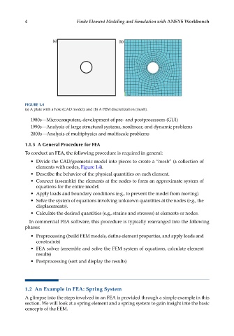
FIGURE 1.4
(a) A plate with a hole (CAD model); and (b) A FEM discretization (mesh).
1980s—Microcomputers, development of pre- and postprocessors (GUI)
1990s—Analysis of large structural systems, nonlinear, and dynamic problems
2000s—Analysis of multiphysics and multiscale problems
1.1.5 A General Procedure for FEA
To conduct an FEA, the following procedure is required in general:
• Divide the CAD/geometric model into pieces to create a “mesh” (a collection of
elements with nodes, Figure 1.4).
• Describe the behavior of the physical quantities on each element.
• Connect (assemble) the elements at the nodes to form an approximate system of
equations for the entire model.
• Apply loads and boundary conditions (e.g., to prevent the model from moving).
• Solve the system of equations involving unknown quantities at the nodes (e.g., the
displacements).
• Calculate the desired quantities (e.g., strains and stresses) at elements or nodes.
In commercial FEA software, this procedure is typically rearranged into the following
phases:
• Preprocessing (build FEM models, define element properties, and apply loads and
constraints)
• FEA solver (assemble and solve the FEM system of equations, calculate element
results)
• Postprocessing (sort and display the results)
1.2 An Example in FEA: Spring System
A glimpse into the steps involved in an FEA is provided through a simple example in this
section. We will look at a spring element and a spring system to gain insight into the basic
concepts of the FEM.