
Page 354 - Finite Element Modeling and Simulations with ANSYS Workbench
P. 354
Introduction to Fluid Analysis 339
analyzed. For more details on numerical solution techniques adopted in CFD, please refer
to the theory guide in ANSYS online documentation.
10.3 Modeling of Fluid Flow
Practical aspects of CFD modeling are discussed next. The topics include fluid domain
specification, meshing, boundary condition assignments, and solution visualization.
10.3.1 Fluid Domain
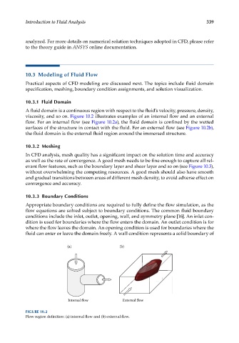
A fluid domain is a continuous region with respect to the fluid’s velocity, pressure, density,
viscosity, and so on. Figure 10.2 illustrates examples of an internal flow and an external
flow. For an internal flow (see Figure 10.2a), the fluid domain is confined by the wetted
surfaces of the structure in contact with the fluid. For an external flow (see Figure 10.2b),
the fluid domain is the external fluid region around the immersed structure.
10.3.2 Meshing
In CFD analysis, mesh quality has a significant impact on the solution time and accuracy
as well as the rate of convergence. A good mesh needs to be fine enough to capture all rel-
evant flow features, such as the boundary layer and shear layer and so on (see Figure 10.3),
without overwhelming the computing resources. A good mesh should also have smooth
and gradual transitions between areas of different mesh density, to avoid adverse effect on
convergence and accuracy.
10.3.3 Boundary Conditions
Appropriate boundary conditions are required to fully define the flow simulation, as the
flow equations are solved subject to boundary conditions. The common fluid boundary
conditions include the inlet, outlet, opening, wall, and symmetry plane [16]. An inlet con-
dition is used for boundaries where the flow enters the domain. An outlet condition is for
where the flow leaves the domain. An opening condition is used for boundaries where the
fluid can enter or leave the domain freely. A wall condition represents a solid boundary of
(a) (b)
Internal flow External flow
FIGURE 10.2
Flow region definition: (a) internal flow and (b) external flow.