
Page 355 - Finite Element Modeling and Simulations with ANSYS Workbench
P. 355
340 Finite Element Modeling and Simulation with ANSYS Workbench
Flow Inadequate mesh Better mesh
FIGURE 10.3
The resolution of a mesh needs to adequately represent the flow feature.
the flow model. For fixed walls, this typically means a no-slip boundary condition for the
flow velocity. A symmetry plane condition is used for planes exhibiting both geometric
and flow symmetry.
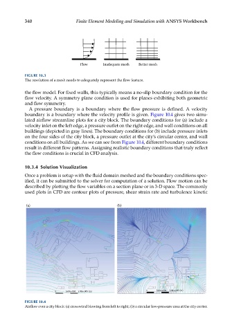
A pressure boundary is a boundary where the flow pressure is defined. A velocity
boundary is a boundary where the velocity profile is given. Figure 10.4 gives two simu-
lated airflow streamline plots for a city block. The boundary conditions for (a) include a
velocity inlet on the left edge, a pressure outlet on the right edge, and wall conditions on all
buildings (depicted in gray lines). The boundary conditions for (b) include pressure inlets
on the four sides of the city block, a pressure outlet at the city’s circular center, and wall
conditions on all buildings. As we can see from Figure 10.4, different boundary conditions
result in different flow patterns. Assigning realistic boundary conditions that truly reflect
the flow conditions is crucial in CFD analysis.
10.3.4 Solution Visualization
Once a problem is setup with the fluid domain meshed and the boundary conditions spec-
ified, it can be submitted to the solver for computation of a solution. Flow motion can be
described by plotting the flow variables on a section plane or in 3-D space. The commonly
used plots in CFD are contour plots of pressure, shear strain rate and turbulence kinetic
(a) (b)
0 5.00e+004 1.00e+005 (m)
0 5.00e+004 1.00e+005 (m)
FIGURE 10.4
Airflow over a city block: (a) crosswind blowing from left to right; (b) a circular low-pressure area at the city center.