
Page 357 - Finite Element Modeling and Simulations with ANSYS Workbench
P. 357
342 Finite Element Modeling and Simulation with ANSYS Workbench
analysis of the air flow passing through a truck. Assume air at room temperature of 25°C
for the flow field with an air velocity of 40 km/hr blowing from left to right. Use non-slip
boundary conditions along the walls of the truck and the ground surface. Find the airflow
pattern as well as the pressure and velocity distributions of the flow field around the truck.
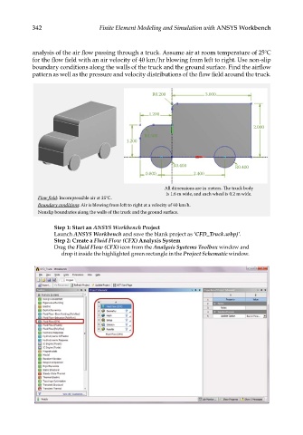
R0.200 3.000
1.200
2.000
R0.500
1.200
R0.400 R0.400
0.800 2.400
All dimensions are in meters. e truck body
is 1.6 m wide, and each wheel is 0.2 m wide.
Flow field: Incompressible air at 25°C.
Boundary conditions: Air is blowing from left to right at a velocity of 40 km/h.
Nonslip boundaries along the walls of the truck and the ground surface.
Step 1: Start an ANSYS Workbench Project
Launch ANSYS Workbench and save the blank project as ‘CFD_Truck.wbpj’.
Step 2: Create a Fluid Flow (CFX) Analysis System
Drag the Fluid Flow (CFX) icon from the Analysis Systems Toolbox window and
drop it inside the highlighted green rectangle in the Project Schematic window.