
Page 37 - Finite Element Modeling and Simulations with ANSYS Workbench
P. 37
22 Finite Element Modeling and Simulation with ANSYS Workbench
FIGURE 2.1
Truss examples: (a) Montreal Biosphere Museum (http://en.wikipedia.org/wiki/Montreal_Biosph%C3%A8re).
(b) Betsy Ross Bridge (http://en.wikipedia.org/wiki/Betsy_Ross_Bridge).
A, E
x P
L
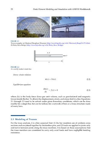
FIGURE 2.2
An axially loaded elastic bar.
Stress–strain relation:
E
x
x
σ() = ε() (2.2)
Equilibrium equation:
σ
dx() + () (2.3)
fx = 0
dx
where f(x) is the body force (force per unit volume, such as gravitational and magnetic
forces) inside the bar. To obtain the displacement, strain, and stress field in a bar, Equations
2.1 through 2.3 need to be solved under given boundary conditions, which can be done
readily for a single bar, but can be tedious for a network of bars or a truss structure made
of many bars.
2.3 Modeling of Trusses
For the truss analysis, it is often assumed that: (1) the bar members are of uniform cross
sections and are joined together by frictionless pins, and (2) loads are applied to joints only
and not in between joints along the truss members. It is based on these assumptions that
the truss members are considered to carry only axial loads and have negligible bending
resistance.