
Page 38 - Finite Element Modeling and Simulations with ANSYS Workbench
P. 38
Bars and Trusses 23
(a) Roof
Purlin
Gusset
(b)
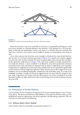
FIGURE 2.3
Modeling of a planar roof truss: (a) Physical structure. (b) Discrete model.
Given the fact that a truss is an assembly of axial bars, it is generally satisfactory to treat
each truss member as a discrete element—bar element. A bar element is a 1-D finite ele-
ment to describe the deformation, strain, and stress in a slender structure member that
often has a uniform cross section and is loaded in tension or compression only along its
axis.
Let us take a planar roof structure as an example to illustrate the truss model idealiza-
tion process. In an actual structure pictured in Figure 2.3a, purlins are used to support
the roof and they further transmit the load to gusset plates that connect the members.
In the idealized model shown in Figure 2.3b, each truss member is simply replaced by a
two-node bar element. A joint condition is modeled by node sharing between elements
connected end-to-end, and loads are imposed only on nodes. Components such as purlins
and gussets are neglected to avoid construction details that do not contribute significantly
to the overall truss load–deflection behavior. Other factors such as the weight of the truss
members can be considered negligible, compared to the loads they carry. If it were to be
included, a member’s weight can always be applied to its two ends, half the weight at each
end node. Experience has shown that the deformation and stress calculations for such
idealized models are often sufficient for the overall design and analysis purposes of truss
structures [3].
2.4 Formulation of the Bar Element
In this section, we will formulate the equations for the bar element based on the 1-D elas-
ticity theory. The structural behavior of the element, or the element stiffness matrix, can be
established using two approaches: the direct approach and the energy approach. The two
methods are discussed in the following.
2.4.1 Stiffness Matrix: Direct Method
A bar element with two end nodes is presented in Figure 2.4.