
Page 40 - Finite Element Modeling and Simulations with ANSYS Workbench
P. 40
Bars and Trusses 25
This can be verified by considering the equilibrium of the forces at the two nodes.
The Element equilibrium equation is
EA 1 − 1 u i f i (2.9)
u j
f j
L − 1 1 =
Degree of Freedom (DOF): Number of components of the displacement vector at a node.
For 1-D bar element along the x-axis, we have one DOF at each node.
Physical Meaning of the Coefficients in k: The jth column of k (here j = 1 or 2) represents the
forces applied to the bar to maintain a deformed shape with unit displacement at node j
and zero displacement at the other node.
2.4.2 Stiffness Matrix: Energy Approach
We derive the same stiffness matrix for the bar using a formal approach which can be
applied to many other more complicated situations.
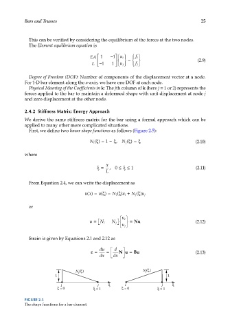
First, we define two linear shape functions as follows (Figure 2.5):
N i ()ξ= 1 −ξ , N j ( )ξ= ξ (2.10)
where
x
ξ= ,0 ≤ξ ≤ 1 (2.11)
L
From Equation 2.4, we can write the displacement as
ux() = u() = N i () u i + N j ()
ξ
ξ
ξ
u j
or
u i
u = N i N j = Nu (2.12)
u j
Strain is given by Equations 2.1 and 2.12 as
du d
ε= = Nu = Bu (2.13)
dx dx
N ( ) N ( )
j
i
1 1
i j i j
= 0 = 1 = 0 = 1
FIGURE 2.5
The shape functions for a bar element.