
Page 39 - Finite Element Modeling and Simulations with ANSYS Workbench
P. 39
24 Finite Element Modeling and Simulation with ANSYS Workbench
u i u j
f i i x A, E j f j
L
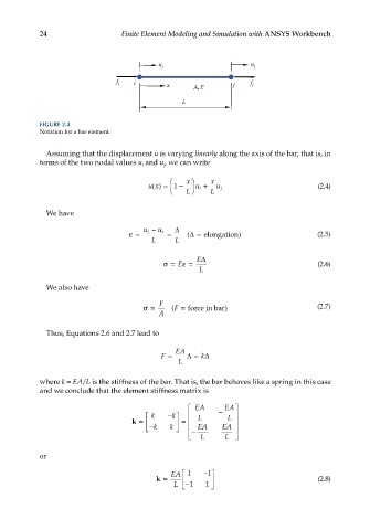
FIGURE 2.4
Notation for a bar element.
Assuming that the displacement u is varying linearly along the axis of the bar, that is, in
terms of the two nodal values u and u, we can write
j
i
x x
ux() = 1 − u i + u j (2.4)
L L
We have
∆
u j
− u i
ε= = ∆ ( = elongation ) (2.5)
L L
E∆
σ= E ε= (2.6)
L
We also have
F
σ= F ( = force in bar ) (2.7)
A
Thus, Equations 2.6 and 2.7 lead to
EA
F = ∆ = k∆
L
where k = EA/L is the stiffness of the bar. That is, the bar behaves like a spring in this case
and we conclude that the element stiffness matrix is
EA − EA
k − k L L
k = =
−k k − EA EA
L L
or
EA 1 − 1
k = (2.8)
L −1 1 