
Page 126 - Flexible Robotics in Medicine
P. 126
112 Chapter 5
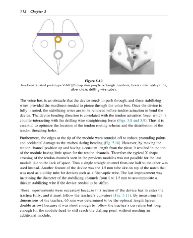
Figure 5.10
Tendon-actuated prototype V-MOJO (top slim purple rectangle: tendons, brass circle: utility tube,
silver circle: drilling wire tube).
The voice box is an obstacle that the device needs to push through, and these stabilizing
wires provided the sturdiness needed to pierce through the voice box. Once the device is
fully inserted, the stabilizing wires are to be removed before tendon actuation to bend the
device. The device bending direction is correlated with the tendon actuation force, which is
counter-interacting with the drilling wire straightening force (Figs. 5.8 and 5.9). Thus it is
essential to optimize the location of the tendon routing scheme and the distribution of the
tendon threading holes.
Furthermore, the edges at the tip of the module were rounded off to reduce protruding points
and accidental damage to the trachea during bending (Fig. 5.10). However, by moving the
tendon channel position up and having a constant length from the pivot, it resulted in the top
of the module having little space for the tendon channels. Therefore the typical X shape
crossing of the tendon channels seen in the previous modules was not possible for the last
module due to the lack of space. Thus a single straight channel from one half to the other was
used instead. Another feature of the device was the 1.5 mm tube slot on top of the notch that
was used as a utility tube for devices such as a fiber-optic wire. The last improvement was
increasing the diameter of the stabilizing channels from 1 to 1.5 mm to accommodate a
thicker stabilizing wire if the device needed to be stiffer.
These improvements were necessary because this section of the device has to enter the
trachea fully, and it must follow the trachea’s curvature (Fig. 5.11). By measuring the
dimensions of the trachea, 65 mm was determined to be the optimal length (green
double arrow) because it was short enough to follow the trachea’s curvature but long
enough for the module head to still reach the drilling point without needing an
additional module.