
Page 282 - Flexible Robotics in Medicine
P. 282
272 Chapter 12
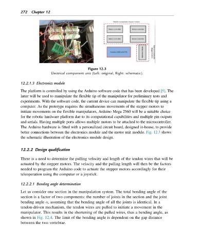
Figure 12.3
Electrical component unit (Left: original, Right: schematic).
12.2.1.3 Electronics module
The platform is controlled by using the Arduino software code that has been developed [5].The
latter will be used to manipulate the flexible tip of the manipulator for preliminary tests and
experiments. With the software code, the current device can manipulate the flexible tip using a
computer. As the prototype requires the simultaneous movements of the stepper motors to
initiate movements on the flexible manipulators, Arduino Mega 2560 will be a suitable choice
for the robotic hardware platform due to its computational capabilities and multiple pin outputs
and serials. Having multiple ports allows multiple motors to be attached to the microcontroller.
The Arduino hardware is fitted with a personalized circuit board, designed in-house, to provide
better connections between the electronics module and the motor unit module. Fig. 12.3 shows
the schematic illustration of the electronics module design.
12.2.2 Design qualification
There is a need to determine the pulling velocity and length of the tendon wires that will be
actuated by the stepper motors. The velocity and the pulling length will then be the factors
needed to program the Arduino code to actuate the stepper motors accordingly for their
teleoperation using the computer or a joystick.
12.2.2.1 Bending angle determination
Let us consider one section in the manipulation system. The total bending angle of the
section is a factor of two components: the number of joints in the section and the joint
bending angle α, assuming that the bending angle of all the joints is identical. In a
tendon-driven mechanism, the tendon wires are pulled to initiate a movement in the
manipulator. This results in the shortening of the pulled wires, thus a bending angle, as
shown in Fig. 12.4. The limit of the bending angle is dependent on the gap distance
between the two vertebrae.