
Page 283 - Flexible Robotics in Medicine
P. 283
Flexible robotic platform with multiple-bending tendon-driven mechanism 273
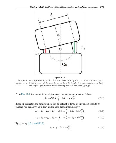
Figure 12.4
Illustration of a single joint in the flexible manipulator bending. d is the distance between two
tendon wires. L 1 is the length of the extending wire. L 2 is the length of the contracting wire. G D is
the original gap distance before bending and α is the bending angle.
From Fig. 12.4, the change in length for each joint can be calculated as follows:
α α
L D 5 d 3 sin 2 2G D 3 sin 2 (12.1)
2 4
Based on geometry, the bending angle can be defined in terms of the tendon’s length by
creating two equations as follows and solving them simultaneously,
α α
L 1 5 G D 1 L D 5 G D 1 d 3 sin 2 2G D 3 sin 2 (12.2)
2 4
α α
L 2 5 G D 2 L D 5 G D 2 d 3 sin 2 2G D 3 sin 2 (12.3)
2 4
By equating (12.1) and (12.2),
α
L 1 2 L 2 5 2d 3 sin (12.4)
2