
Page 288 - Flexible Robotics in Medicine
P. 288
278 Chapter 12
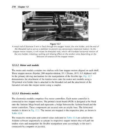
Figure 12.7
A metal rod of diameter 3 mm is fixed through the stepper motor, the wire holder, and the end of
the threaded rod to act as a stabilizer to prevent any unnecessary rotational motion. As the
stepper motor rotates, it will rotate the threaded rods, which will translate horizontal motion of
the wire holder, initiating a pulling and relaxing effect on the tendon wires depending on the
direction of rotation of the stepper motor.
12.3.2 Motor unit module
The motor unit module contains two shelves with four stepper motors aligned on each shelf.
These stepper motors (bipolar, 200 steps/revolution, 35 3 28 mm, 10 V, 0.5 A/phase) will
be the primary driving mechanism for the manipulation of the flexible tips. Fig. 12.7
demonstrates the attachment of the tendon wires onto the motor unit module using a
3D-printed wire holder that is attached to the threaded rod and the attachment of the
threaded rod onto the stepper motor using a coupler.
12.3.3 Electronics module
The electronics module comprises five motor controllers. Each motor controller is
connected to two stepper motors. The printed circuit board (PCB) is designed to be fitted
onto the Arduino Mega board and represents a bridge between the Arduino board and the
motor controllers. These components are secured onto an acrylic base. The fabricated
module is shown in Fig. 12.2. The motors are mapped to the respective pins, as shown in
Table 12.4.
The respective motor pins and control values indicated in Table 12.4 are called in the
Arduino software sequentially to actuate its respective stepper motors that will pull the
tendon wires and manipulate the flexible manipulator arms accordingly to the user’s
commands by computer or joystick.