
Page 286 - Flexible Robotics in Medicine
P. 286
276 Chapter 12
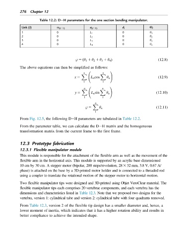
Table 12.2: D H parameters for the one section bending manipulator.
Link (i) α (i21) a (i21) d i Θ i
1 0 L 1 0 θ 1
2 0 L 2 0 θ 2
3 0 L 3 0 θ 3
4 0 L 4 0 θ 4
ð
ϕ 5 θ 1 1 θ 2 1 θ 3 1 θ 4 Þ (12.8)
The above equations can then be simplified as follows:
!
n n
X X
x 5 L n cos θ n (12.9)
1 1
!
n n
X X
y 5 L n sin θ n (12.10)
1 1
n
X
ϕ 5 θ n (12.11)
1
From Fig. 12.5, the following D H parameters are tabulated in Table 12.2.
From the parameter table, we can calculate the D H matrix and the homogeneous
transformation matrix from the current frame to the first frame.
12.3 Prototype fabrication
12.3.1 Flexible manipulator module
This module is responsible for the attachment of the flexible arm as well as the movement of the
flexible arm in the horizontal axis. This module is supported by an acrylic base dimensioned
10 cm by 30 cm. A stepper motor (bipolar, 200 steps/revolution, 283 32 mm, 3.8 V, 0.67 A/
phase) is attached on the base by a 3D-printed motor holder and is connected to a threaded rod
using a coupler to translate the rotational motion of the stepper motor to horizontal motion.
Two flexible manipulator tips were designed and 3D-printed using Objet VeroClear material. The
flexible manipulator tips each comprises 20 vertebrae components, and each vertebra has the
dimensions and characteristics listed in Table 12.3. Note that we proposed two designs for the
vertebra, version 1: cylindrical tube and version 2: cylindrical tube with four quadrants removed.
From Table 12.3, version 2 of the flexible tip design has a smaller diameter and, hence, a
lower moment of inertia, which indicates that it has a higher rotation ability and results in
better compliance to achieve the intended shape.