
Page 289 - Flexible Robotics in Medicine
P. 289
Flexible robotic platform with multiple-bending tendon-driven mechanism 279
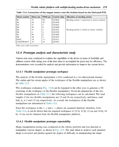
Table 12.4: Connections of the stepper motors onto the Arduino board via the fabricated PCB.
Motor number Motor pin PWM pin Control value Allocation on bending section
B1 21 46 OCR5A Bending section 1 (proximal to motor module)
B2 20 45 OCR5B
B3 51 7 OCR4C
B4 50 8 OCR4B
B5 47 3 OCR3C Bending section 2 (distal to motor module)
B6 4 2 OCR3B
B7 49 6 OCR4A
B8 48 5 OCR3A
BASE 18 13 OCR1C
CONSTRAINT 19 44 OCR5C
PWM, pulse width modulation.
12.4 Prototype analysis and characteristic study
Various tests were conducted to evaluate the capabilities of the device in terms of flexibility and
stiffness control while taking note of the time taken to accomplish the given task for efficiency. The
demonstrations were recorded for analysis and provide information to improve the current device.
12.4.1 Flexible manipulator prototype workspace
The analysis of the flexible manipulator is first conducted in a two-dimensional manner.
The radius and the sweep angles of the workspace of the flexible manipulator are as shown
in Table 12.5.
This workspace evaluation (Fig. 12.8) can be repeated in the other axes to generate a 3D
rendering of the workspace of the flexible manipulator. Given the dimensions of the two
flexible manipulators in Table 12.3, the following workspaces can be calculated. The total
lengths of the two flexible manipulators are 12 and 16 cm, respectively, and hence, each
link, L n is 3 and 3.5 cm, respectively. As a result, the workspaces of the flexible
manipulator are determined in Table 12.6.
Since the workspace in the x y and x z planes are assumed identical; therefore, from
Table 12.6, it can be shown that the required workspace of 12 by 12 by 12 cm and 14 by 14
by 14 cm can be obtained from the flexible manipulator platform.
12.4.2 Flexible manipulator prototype repeatability
Shape manipulation testing was conducted on the robotic platform and was directed to
manipulate various shapes, as shown in Fig. 12.9. The time taken to achieve each intended
shape is recorded and plotted against the degree of difficulty in manipulating the shape.