
Page 287 - Flexible Robotics in Medicine
P. 287
Flexible robotic platform with multiple-bending tendon-driven mechanism 277
Table 12.3: Properties of the flexible tip vertebrae.
Outer diameter 10 mm
Inner diameter 3 mm
Tendon wire hole diameter 1 mm
Mass 0.82 g
2
Moment of inertia Ixx:Izz 0.257 gcm :0.447 gcm 2
Outer diameter 8 mm
Inner diameter 2 mm
Tendon wire hole diameter 1 mm
Mass 0.68 g
2
Moment of inertia Ixx:Izz 0.130 gcm :0.227 gcm 2
Note that the moment of inertia is calculated assuming that the structure for version 1 is a cylindrical tube, whereas
version 2 is assumed to be a cylindrical tube with four quadrants removed.
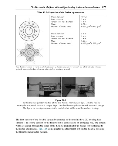
Figure 12.6
The flexible manipulator module of the two flexible manipulator tips. Left: the flexible
manipulator tip with version 1 design; Right: the flexible manipulator tip with version 2 design.
The figure on the right represents the module that will be used for cadaver testing.
The first version of the flexible tip can be attached to the module by a 3D printing base
support. The second version of the flexible tip is connected to an elongated rod. The tendon
wires are driven through the holes of the flexible manipulator tip bodies to be attached to
the motor unit module. Fig. 12.6 demonstrates the attachment of both the flexible tips onto
the flexible manipulator module.