
Page 304 - Flexible Robotics in Medicine
P. 304
294 Chapter 13
main elements: the main conduit and the connector ring. These two elements, when joined
together, form the flexible modular vase-spine design. Both the elements consist of four
small lumens of 0.3 mm and a middle larger lumen. The four small lumens are channels for
cables to pass through in order to control the bending of the distal tip. At the distal end of
the vase-spine bending section, the camera holder is attached and at the proximal end, the
connector tube shaft is attached. The combination of all of the above elements will form the
nasopharyngoscope assembly.
This nasopharyngoscope assembly is then attached to a gear rack, which is then attached to
a gear on a horizontally placed stepper motor that controls the translation motion of the
nasopharyngoscope. There are two more stepper motors placed vertically with axles on the
shaft. This axle contains holes where the cables controlling the flexible distal tip are tied to.
By means of rotating the axles, the flexible distal tip will bend to the left, right, up, or
down depending on the motor turned. One motor would control the up and down
movement, whereas the other controls the left and right movements. All the elements are
placed onto a portable yet sturdy frame with all the elements combined with manipulator
features of a wide viewing sphere for surveillance and portability.
13.3.1 Design process
The final design for BEE was achieved after an iterative procedure via modification from an
initial base design through several stages. From the initial design phase until the final design
phase, we used a modular two-part design for the implementation of the flexible tip of BEE. It
was termed the flexible vase-spine modular design due to the resemblance of the design to a
typical vase and how the modules were adjoined to each other with the likeness of an animal’s
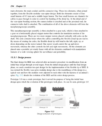
spine. Fig. 13.2 details the evolution of the BEE and the entire design process.
Prototype 1.0 was a crude prototype, but it served the purpose of being the initial base
design upon which the evolution of the prototypes took place. As can be seen, prototype 1.0
Prototype 1.0 Prototype 2.0 Prototype 3.0
Prototype 4.0 Prototype 5.0 Prototype 6.0 Prototype 7.0
Figure 13.2
Design evolution of prototypes.