
Page 307 - Flexible Robotics in Medicine
P. 307
Design evolution of a flexible robotic bending end-effector for transluminal explorations 297
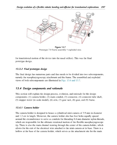
Figure 13.7
Prototype 7.0 frame assembly 1 exploded view.
for translational motion of the device into the nasal orifice). This was the final
prototype design.
13.3.2 Final prototype design
The final design has numerous parts and thus needs to be divided into two subcomponents,
namely the nasopharyngoscopy attachment and the frame. The assembled and exploded
views of both subcomponents are illustrated in Figs. 13.6 and 13.7.
13.4 Design components and rationale
This section will explain the design process, evolution, and rationale for the design
components: (1) camera holder, (2) main conduit, (3) connector, (4) connector tube shaft,
(5) stepper motor (to scale model), (6) axle, (7) gear rack, (8) gear, and (9) frame.
13.4.1 Camera holder
The camera holder is designed to house a cylindrical mini-camera of 3.9 mm in diameter
and 1.2 cm in length. Moreover, the camera holder also has four holes equally spaced
around the circumference to serve as conduits for threading 0.4 mm diameter nylon threads,
which are responsible for the ultimate rotational motion of the flexible nasopharyngoscope
tip. There is also the main channel running through the center of the camera holder, which
allows for the exit of the electrical wire attached to the mini-camera at its base. There is a
hollow at the base of the camera holder, which serves as the attachment site for the main