
Page 309 - Flexible Robotics in Medicine
P. 309
Design evolution of a flexible robotic bending end-effector for transluminal explorations 299
flexible manipulator designs. The evolution of the main conduit module is shown in
Fig. 13.10.
There are three main differences we can immediately observe as the design progresses: (1)
the design adopts a less angular and more rounded conformation, (2) the design “narrows”
at the top and bottom ends, and (3) the design “widens” relative to the ends at the central
disc shaped region.
The rounded conformation of the design was adopted in accordance with design acceptance
criterion 1 (Section 13.4.1). As for the change in geometry of the design, it was designed as
such to fulfill design acceptance criteria 2, 3, and 10 (Section 13.4.1).
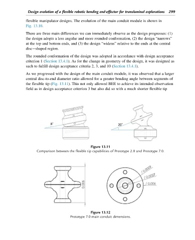
As we progressed with the design of the main conduit module, it was observed that a larger
central disc-to-end diameter ratio allowed for a greater bending angle between segments of
the flexible tip (Fig. 13.11). This not only allowed BEE to achieve its intended observation
field as in design acceptance criterion 3 but also did so with a much shorter flexible tip
Figure 13.11
Comparison between the flexible tip capabilities of Prototype 2.0 and Prototype 7.0.
Figure 13.12
Prototype 7.0 main conduit dimensions.