
Page 310 - Flexible Robotics in Medicine
P. 310
300 Chapter 13
length, thus allowing it to carry out an equivalent function more effectively as per design
acceptance criterion 10. Furthermore, this modification in design does not compromise
design acceptance criterion 2, as the segments still fit securely within each other, kept in
place by the nylon threads, which run the entire length of the flexible tip.
The dimensions for the main conduit module and relevant illustrations are shown in
Fig. 13.12.
13.4.3 Connector
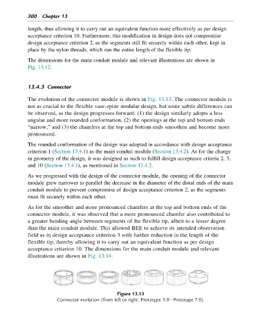
The evolution of the connector module is shown in Fig. 13.13. The connector module is
not as crucial to the flexible vase-spine modular design, but some subtle differences can
be observed, as the design progresses forward: (1) the design similarly adopts a less
angular and more rounded conformation, (2) the openings at the top and bottom ends
“narrow,” and (3) the chamfers at the top and bottom ends smoothen and become more
pronounced.
The rounded conformation of the design was adopted in accordance with design acceptance
criterion 1 (Section 13.4.1) as the main conduit module (Section 13.4.2). As for the change
in geometry of the design, it was designed as such to fulfill design acceptance criteria 2, 3,
and 10 (Section 13.4.1), as mentioned in Section 13.4.2.
As we progressed with the design of the connector module, the opening of the connector
module grew narrower to parallel the decrease in the diameter of the distal ends of the main
conduit module to prevent compromise of design acceptance criterion 2, as the segments
must fit securely within each other.
As for the smoother and more pronounced chamfers at the top and bottom ends of the
connector module, it was observed that a more pronounced chamfer also contributed to
a greater bending angle between segments of the flexible tip, albeit to a lesser degree
than the main conduit module. This allowed BEE to achieve its intended observation
field as in design acceptance criterion 3 with further reduction in the length of the
flexible tip, thereby allowing it to carry out an equivalent function as per design
acceptance criterion 10. The dimensions for the main conduit module and relevant
illustrations are shown in Fig. 13.14.
Figure 13.13
Connector evolution (from left to right: Prototype 1.0 Prototype 7.0).