
Page 313 - Flexible Robotics in Medicine
P. 313
Design evolution of a flexible robotic bending end-effector for transluminal explorations 303
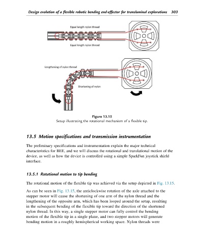
Figure 13.15
Setup illustrating the rotational mechanism of a flexible tip.
13.5 Motion specifications and transmission instrumentation
The preliminary specifications and instrumentation explain the major technical
characteristics for BEE, and we will discuss the rotational and translational motion of the
device, as well as how the device is controlled using a simple SparkFun joystick shield
interface.
13.5.1 Rotational motion to tip bending
The rotational motion of the flexible tip was achieved via the setup depicted in Fig. 13.15.
As can be seen in Fig. 13.15, the anticlockwise rotation of the axle attached to the
stepper motor will cause the shortening of one arm of the nylon thread and the
lengthening of the opposite arm, which has been looped around the setup, resulting
in the subsequent bending of the flexible tip toward the direction of the shortened
nylon thread. In this way, a single stepper motor can fully control the bending
motion of the flexible tip in a single plane, and two stepper motors will generate
bending motion in a roughly hemispherical working space. Nylon threads were