
Page 308 - Flexible Robotics in Medicine
P. 308
298 Chapter 13
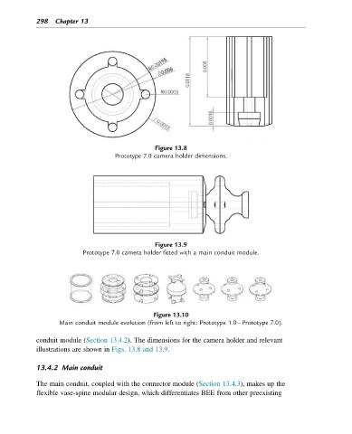
Figure 13.8
Prototype 7.0 camera holder dimensions.
Figure 13.9
Prototype 7.0 camera holder fitted with a main conduit module.
Figure 13.10
Main conduit module evolution (from left to right: Prototype 1.0 Prototype 7.0).
conduit module (Section 13.4.2). The dimensions for the camera holder and relevant
illustrations are shown in Figs. 13.8 and 13.9.
13.4.2 Main conduit
The main conduit, coupled with the connector module (Section 13.4.3), makes up the
flexible vase-spine modular design, which differentiates BEE from other preexisting