
Page 305 - Flexible Robotics in Medicine
P. 305
Design evolution of a flexible robotic bending end-effector for transluminal explorations 295
Connector segments
Main conduit
Figure 13.3
Prototype 1.0 modules.
Camera
Connector segments
Main conduit
Connector tube shaft
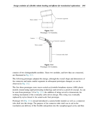
Figure 13.4
Prototype 4.0 modules.
consists of two distinguishable modules. These two modules, and how they are connected,
are illustrated in Fig. 13.3.
The following prototypes adopted this design, although the overall shape and dimensions of
the connector and main conduit segments in subsequent prototypes changed, as can be
observed in Fig. 13.2.
The first three prototypes were macro-scaled acrylonitrile butadiene styrene (ABS) plastic
models created using rapid prototyping technology and served as a proof-of-concept. As can
be seen from prototype 3.0 in Fig. 13.2, the addition of string served to demonstrate the
working mechanism of the eventually cable-driven design. This string was eventually
replaced by nylon thread in the actual-scale final prototype.
Prototype 4.0 (Fig. 13.4) onward introduced a camera holder module as well as a connector
tube shaft into the design. The purpose of the connector tube shaft was to aid in the
translation and delivery of the flexible end-portion into the nasopharyngeal cavity and thus