
Page 220 - Fluid Mechanics and Thermodynamics of Turbomachinery
P. 220
Centrifugal Pumps, Fans and Compressors 201
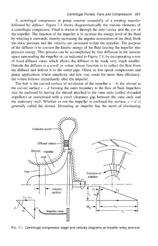
A centrifugal compressor or pump consists essentially of a rotating impeller
followed by diffuser. Figure 7.1 shows diagrammatically the various elements of
a centrifugal compressor. Fluid is drawn in through the inlet casing into the eye of
the impeller. The function of the impeller is to increase the energy level of the fluid
by whirling it outwards, thereby increasing the angular momentum of the fluid. Both
the static pressure and the velocity are increased within the impeller. The purpose
of the diffuser is to convert the kinetic energy of the fluid leaving the impeller into
pressure energy. This process can be accomplished by free diffusion in the annular
space surrounding the impeller or, as indicated in Figure 7.1, by incorporating a row
of fixed diffuser vanes which allows the diffuser to be made very much smaller.
Outside the diffuser is a scroll or volute whose function is to collect the flow from
the diffuser and deliver it to the outlet pipe. Often, in low-speed compressors and
pump applications where simplicity and low cost count for more than efficiency,
the volute follows immediately after the impeller.
The hub is the curved surface of revolution of the impeller a b; the shroud is
the curved surface c d forming the outer boundary to the flow of fluid. Impellers
may be enclosed by having the shroud attached to the vane ends (called shrouded
impellers) or unenclosed with a small clearance gap between the vane ends and
the stationary wall. Whether or not the impeller is enclosed the surface, c d is
generally called the shroud. Shrouding an impeller has the merit of eliminating
FIG. 7.1. Centrifugal compressor stage and velocity diagrams at impeller entry and exit.