
Page 221 - Fluid Mechanics and Thermodynamics of Turbomachinery
P. 221
202 Fluid Mechanics, Thermodynamics of Turbomachinery
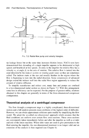
FIG. 7.2. Radial-flow pump and velocity triangles.
tip leakage losses but at the same time increases friction losses. NACA tests have
demonstrated that shrouding of a single impeller appears to be detrimental at high
speeds and beneficial at low speeds. At entry to the impeller the relative flow has a
velocity w 1 at angle ˇ 1 to the axis of rotation. This relative flow is turned into the
axial direction by the inducer section or rotating guide vanes as they are sometimes
called. The inducer starts at the eye and usually finishes in the region where the
flow is beginning to turn into the radial direction. Some compressors of advanced
design extend the inducer well into the radial flow region apparently to reduce the
amount of relative diffusion.
To simplify manufacture and reduce cost, many fans and pumps are confined
to a two-dimensional radial section as shown in Figure 7.2. With this arrangement
some loss in efficiency can be expected. For the purpose of greatest utility, relations
obtained in this chapter are generally in terms of the three-dimensional compressor
configuration.
Theoretical analysis of a centrifugal compressor
The flow through a compressor stage is a highly complicated, three-dimensional
motion and a full analysis presents many problems of the highest order of difficulty.
However, we can obtain approximate solutions quite readily by simplifying the flow
model. We adopt the so-called one-dimensional approach which assumes that the
fluid conditions are uniform over certain flow cross-sections. These cross-sections
are conveniently taken immediately before and after the impeller as well as at inlet
and exit of the entire machine. Where inlet vanes are used to give prerotation to the
fluid entering the impeller, the one-dimensional treatment is no longer valid and an
extension of the analysis is then required (see Chapter 6).