
Page 222 - Fluid Mechanics and Thermodynamics of Turbomachinery
P. 222
Centrifugal Pumps, Fans and Compressors 203
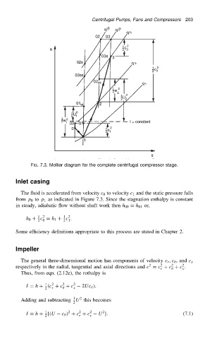
FIG. 7.3. Mollier diagram for the complete centrifugal compressor stage.
Inlet casing
The fluid is accelerated from velocity c 0 to velocity c 1 and the static pressure falls
from p 0 to p 1 as indicated in Figure 7.3. Since the stagnation enthalpy is constant
in steady, adiabatic flow without shaft work then h 00 D h 01 or,
1 2
1 2
h 0 C c D h 1 C c .
2 0 2 1
Some efficiency definitions appropriate to this process are stated in Chapter 2.
Impeller
The general three-dimensional motion has components of velocity c r ,c , and c x
2
2
2
2
respectively in the radial, tangential and axial directions and c D c C c C c .
r x
Thus, from eqn. (2.12e), the rothalpy is
1
2
2
I D h C .c C c C c 2 2Uc /.
2 r x
2
1
Adding and subtracting U this becomes
2
1
2
2
2
I D h C f.U c / C c C c 2 U g. (7.1)
2 r x