
Page 109 - Fluid Power Engineering
P. 109
Hydraulic Transmission Lines 83
FIGURE 3B.3 Scheme of the line connection.
• The DCV (a) is switched to the closed position.
• The DCV (b) is switched to the opened position, and then to
the closed position. The pressure in the tested line is thus
equal to the tank pressure.
• The DCV (a) is rapidly switched to the open position to
communicate the constant pressure source (447 bar) with the
line inlet. The pressure at the line end P(L) is then recorded.
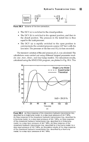
The transient variation of the end pressure p(L,t), was calculated. The
calculations were carried out using different lumped parameter mod-
els: one-, two-, three-, and four-lump models. The simulation results,
calculated using the SIMULINK program, are plotted in Fig. 3B.4. This
(a)
FIGURE 3B.4 (a) Step response of the closed-end hydraulic transmission line,
described by a single-lump model, to a step input pressure of 44.7 MPa.
(b) Step response of the closed-end hydraulic transmission line, described by
a two-lump model, to a step input pressure of 44.7 MPa. (c) Step response
of the closed-end hydraulic transmission line, described by a three-lump
model, to a step input pressure of 44.7 MPa. (d) Step response of the
closed-end hydraulic transmission line, described by a four-lump model, to a
step input pressure of 44.7 MPa. (e) Simulation results of the step response
of the closed-end hydraulic transmission line, described by a four-lump
model, to a step input pressure of 44.7 MPa.