
Page 155 - Fluid Catalytic Cracking Handbook
P. 155
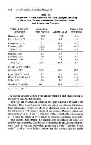
130   Fluid Catalytic Cracking Handbook

                            Table 4-3
      Comparison of Yield Structure for Fluid Catalytic Cracking
        of Waxy Gas Oil over Commercial Equilibrium Zeolite
                     and Amorphous Catalysts


  Yields, at 80 vol%    Amorphous,                    Change from
     Conversion         High Alumina   Zeolite, XZ-25  Amorphous
 Hydrogen, wt%              0.08            0.04         -0.04
 C 1's + C 2's, wt%         3.8             2.1          -1.7
 Propylene, vol%           16.1            11.8          -4.3
 Propane, vol%              1.5             1.3          -0.02
  Total C 3's              17.6            13.1          -4.5
 Butenes, vol%             12.2             7.8          -4.4
 i-Butane, vol%             7.9             7.2          -0.7
 n-Butane, vol%             0,7             0.4          -0.3
  Total C 4's              20.8            15.4          -5.4
 C 5-390 at 90% ASTM
 gasoline, vol%            55.5            62.0          +6.5
 Light Fuel Oil, vol%       4.2             6.1          +1.9
 Heavy Fuel Oil, vol%      15.8            13.9          -1.9
 Coke, wt%                  5.6             4.1          -1.5

 Gasoline Octane No.       94              89.8          -4.2
 Source: Venuto [2]


 The higher activity comes from greater strength and organization of
 the active sites in the zeolites.
  Zeolites are crystalline alumina-silicates having a regular pore
 structure. Their basic building blocks are silica and alumina tetrahedra.
 Each tetrahedron consists of silicon or aluminum atoms at the center of
 the tetrahedron with oxygen atoms at the corners. Because silicon and
 aluminum are in a +4 and 4-3 oxidation state, respectively, a net charge
 of -1 must be balanced by a cation to maintain electrical neutrality.
  The cations that replace the sodium ions determine the catalyst's
 activity and selectivity. Zeolites are synthesized in an alkaline environ-
 ment such as sodium hydroxide, producing a soda-Y zeolite. These
 soda-Y zeolites have little stability but the sodium can be easily